


Hyster T1.0, T1.2, T1.5 Electric Forklift Truck A462 Series Repair Manual
$30.00
Repair Manual for Hyster A462 Series, Models: T1.0, T1.2, T1.5
Format: PDF
English
- Hyster T1.0, T1.2, T1.5 Electric Forklift Truck A462 Series Repair Manual: 278 Pages
- Description
- Reviews (0)
Description
Hyster T1.0, T1.2, T1.5 Electric Forklift Truck A462 Series Repair Manual
Repair Manual for Hyster A462 Series, Models: T1.0, T1.2, T1.5
Format: PDF
English
- Hyster T1.0, T1.2, T1.5 Electric Forklift Truck A462 Series Repair Manual: 278 Pages
Hyster A462 Series, Models: T1.0, T1.2, T1.5 Manual Table Of Content:
Section: Electrical System
– Standard Electrical Diagrams
– Functional Electrical Diagram With Wire Guidance System Models T1.0 – 1.2 – 1.5
– Functional Electrical Diagram Of The Solenoid Valves Prc Controller
– Functional Electrical Diagram
– Functional Electrical Diagram Of Electric Steering With Wire Guidance System
– Key To Electrical And Connector Diagrams
– Electrical Components Models T1.0 – 1.2 – 1.5
– Standard Functional Electrical Diagram Models T1.0 – 1.2 – 1.5 Models T1.0 – 1.2 – 1.5
– Functional Electrical Diagram Of The Solenoid Valves Prc Controller
– Functional Electrical Diagram
– Key To Electrical Diagrams Of Components
– Electrical Diagrams With Wire Guidance
1.0 Table Of Electrical Components
1.1 Electrical Components
1.2 Position Of Relays Bank
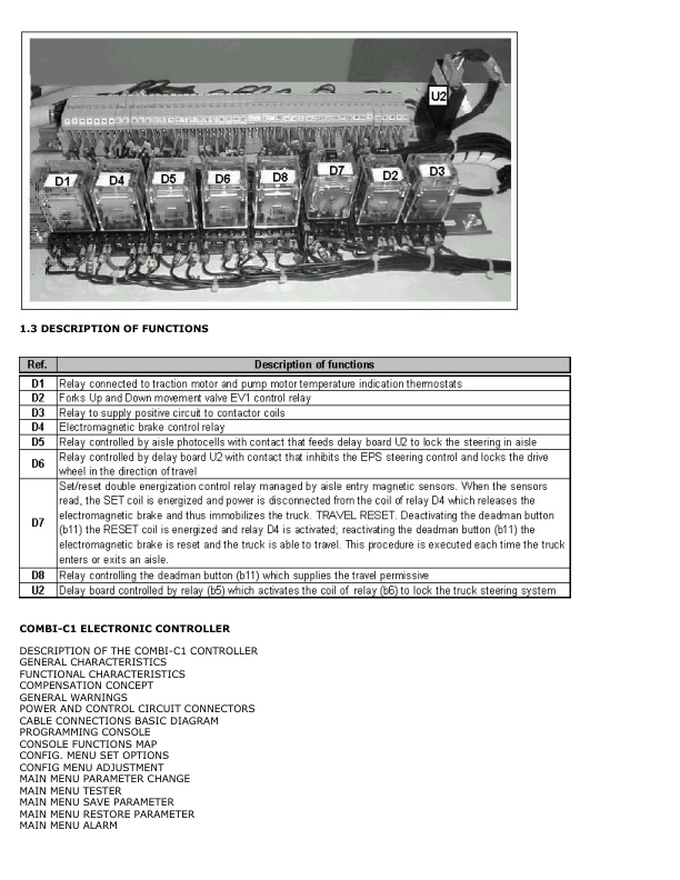
1.3 Description Of Relay Functions Combi-C1 Controller
1.0 Description Of Combi-C1 Electronic Controller
1.2 Technical Specifications
1.3 Schematic Diagram
1.4 Functional Characteristics
1.5 Compensation Concept
1.7 General Warnings And Precautions
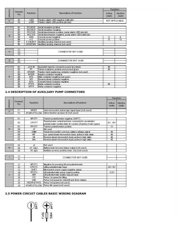
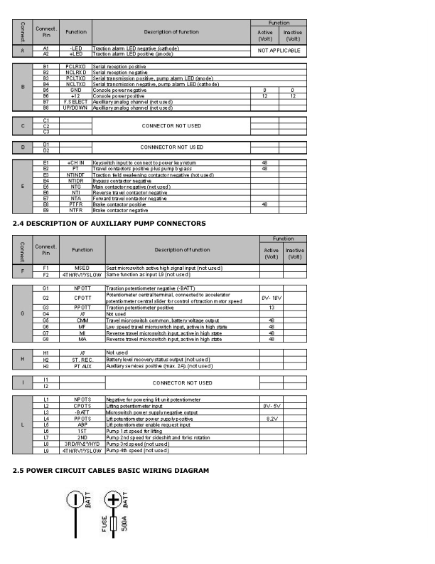
2.0 Power And Control Circuit Connectors
2.6 Power Cables Connection Diagram
3.0 Programming Console
4.0 Console Functions Map
5.0 Controller Programming
5.1 Config. Menu Set Options
5.2 Config. Menu Adjustment
5.3 Main Menu Parameter Change
5.4 Main Menu Tester
5.5 Main Menu Save Parameter
5.6 Main Menu Restore Parameter
5.7 Main Menu Alarm
5.8 Main Menu Program Vacc
6.0 Combi-C1 Controller Configuration Tables
7.0 Calibration Sequence For Initialization Of A New Controller
7.2 Pump Unit Calibration Sequence
8.0 Troubleshooting
8.1 Decoding Traction System Diagnostic Led Alarm Signals
8.2 Decoding Of Alarms Displayed On The Console (Traction)
9.1 Decoding Of Pump Unit Diagnostic Led Alarms
9.2 Decoding Of Alarms Displayed On The Console (Pump Unit)
Section: Prc Hydraulic Controller
1.0 Introduction To Prc Controller
2.0 Console Functions Map
3.0 Prc Controller Configuration Table
4.0 Configuration Of Potentiometers On Prc
4.1 Description Of Parameters
5.0 Description Of Alarms
6.0 Program Vacc Section: Hydraulic System
Section: Hydraulic System
1.0 Functional Hydraulic Diagram
1.1 Table Of Hydraulic Components
1.2 Table Of Hydraulic Components
1.3 Mast Lift – Hydraulic Circuit Status
1.4 Mast Lower – Hydraulic Circuit Status
1.5 Forks Right-Hand Sideshift – Hydraulic Circuit Status
1.6 Forks Left-Hand Sideshift – Hydraulic Circuit Status
1.7 Forks Right-Hand Rotation Hydraulic Circuit Status
1.8 Forks Left-Hand Rotation Hydraulic Circuit Status
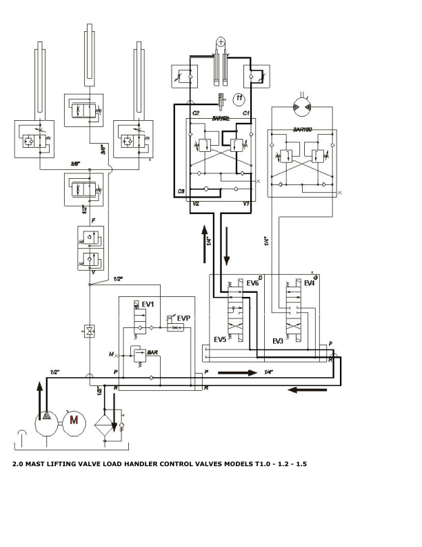
2.0 Mast Lift/Lower And Load Handler Control Valves
2.1 Table Of Valve Components Section: Load Handler
Section: Three-Sided Load Handler
1.0 Standard Load Handler Components
1.1 Table Of Standard Load Handler Components
1.2 Components Of Load Handler With Carriage
1.3 Table Of Load Handler Components With Carriage
2.0 Load Handler Function
2.1 Installation Of Load Handler With Carriage
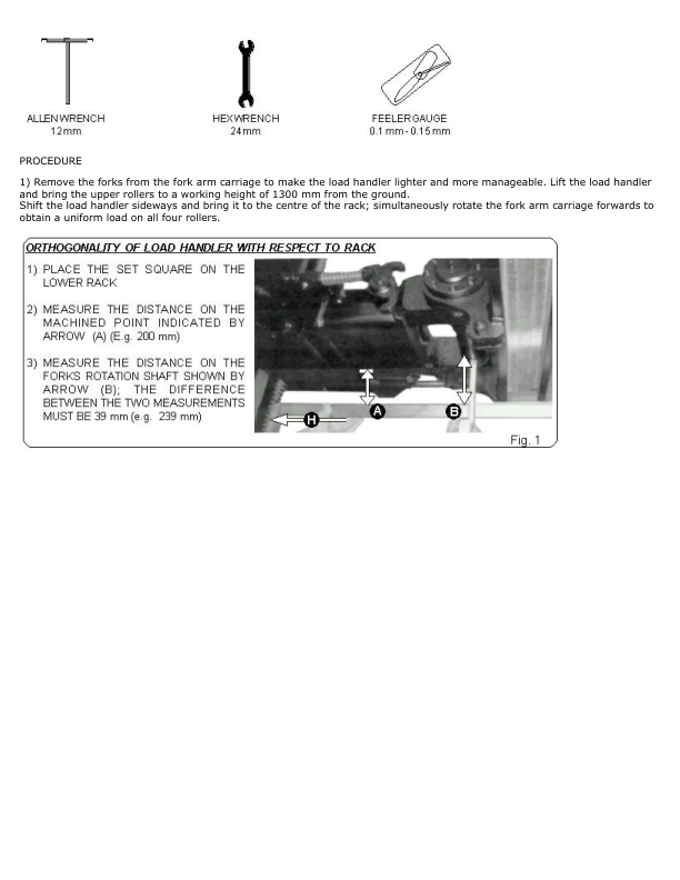
2.2 Mechanical Adjustment Of Limit Positions
2.5 Maintenance
2.6 Troubleshooting
3.0 Mechanical Adjustment Of The Load Handler Bearings
Section: Truck Installation
1.0 Installing The Truck
2.0 Truck Operating Conditions Outside And Inside Aisle
2.1 Description Of Truck Operation Outside And Inside Aisle
3.0 Installing Truck In Aisle
4.0 Wide Guidance Adjustment Procedure
5.0 Layout For Positioning Of Magnets In Aisle
6.0 Layout For Positioning Of Guides In Aislereducer Manuallevel Preselector Manualeps-Dc / Wire Guidance
The Service Repair Manual are updated on a regular basis, but may not reflect recent design changes to the product. Updated technical service information may be available from our website.
The Service Repair Manual provide general guidelines for maintenance and service of the A462 Series, Models: T1.0, T1.2, T1.5and are intended for use by trained and experienced technicians. Failure to properly maintain equipment or to follow instructions contained in the Service Manual could result in damage to the products, personal injury, property damage or death.
• When lifting parts or assemblies, make sure all slings, chains, or cables are correctly fastened, and that the load being lifted is balanced. Make sure the crane, cables, and chains have the capacity to support the weight of the load.
• Do not lift heavy parts by hand, use a lifting mechanism.
• Wear safety glasses.
• DISCONNECT THE BATTERY CONNECTOR before doing any maintenance or repair on electric lift trucks. Disconnect the battery ground cable on internal combustion lift trucks.
• Always use correct blocks to prevent the unit from rolling or falling. See HOW TO PUT THE LIFT TRUCK ON BLOCKS in the Operating Manual or the Periodic Maintenance section.
Caution:
• Always fasten a DO NOT OPERATE tag to the controls of the unit when making repairs, or if the unit needs repairs.
• Be sure to follow the WARNING and CAUTION notes in the instructions.
• Gasoline, Liquid Petroleum Gas (LPG), Compressed Natural Gas (CNG), and Diesel fuel are flammable.
• Be sure to follow the necessary safety precautions when handling these fuels and when working on these fuel systems.
• Batteries generate flammable gas when they are being charged. Keep fire and sparks away from the area. Make sure the area is well ventilated.
Be the first to review “Hyster T1.0, T1.2, T1.5 Electric Forklift Truck A462 Series Repair Manual”
You must be logged in to post a review.

Reviews
There are no reviews yet.