


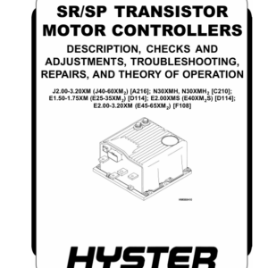
Hyster K1.0H Order Picker A460 Series Repair Manual
$35.00
Repair Manual for Hyster A460 Series, Model: K1.0H
Format: PDF
English
- Hyster K1.0H Order Picker A460 Series Repair Manual: 380 Pages
- Description
- Reviews (0)
Description
Hyster K1.0H Order Picker A460 Series Repair Manual
Repair Manual for Hyster A460 Series, Model: K1.0H
Format: PDF
English
- Hyster K1.0H Order Picker A460 Series Repair Manual: 380 Pages
Hyster A460 Series, Model: K1.0H Manual Table Of Content:
Section: Electrical System
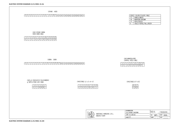
– Electric System Diagram Mod. K1.0L
1.0 Motor Compartment Components K1.0L
1.1 Motor Compartment Components K0.6M-K1.0M
1.2 Motor Compartment Components K1.0H
1.3 Components On The Machine K1.0L-12
1.4 Components On The Machine K1.0L-20
1.5 Components On The Machine K1.0L-12/20
1.6 Position Of Components On The Machine
1.7 Position Of The Electric Steering K0.6M-K1.0M
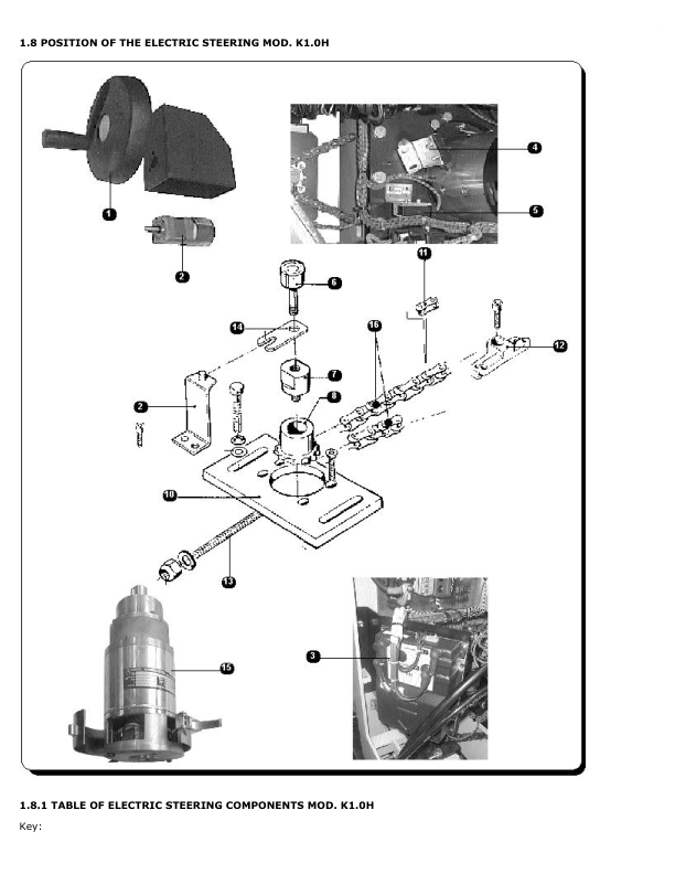
1.8 Position Of The Electric Steering K1.0H
1.9 Console Components
1.10 Drive System Components K1.0L
1.11 Drive And Lifting System Components K0.6M-K1.0M
1.12 Drive And Lifting System Components K1.0H
2.0 Electronic Drive Motor Control
2.1 Definition Of The Direction Of Travel Of The Machine
2.2 General Characteristics Of The Chopper H2B
2.3 Functional Characteristics Of The Chopper
2.4 Self-Diagnosis For Chopper H2-400A
2.5 Mechanical Drawing Of Chopper H2B
2.6 Connectors
2.7 Description Of Connector “B” Inputs
2.8 Description Of Connector “E” Inputs
2.9 Chopper Connections Diagram
3.0 Programming Console
3.1 Introduction
3.2 Use Of The Programming Console
3.3 Console Functions Chart
3.4 Programming The Chopper
3.5 Configuration Menu/Set Model
3.6 Configuration Menu/Set Options
3.7 Main Menu/Adjustment
3.8 Main Menu/Parameter Change
3.9 Main Menu/Tester
3.10 Main Menu/Save Parameter
3.11 Main Menu/Restore Parameter
3.12 Main Menu/Alarm
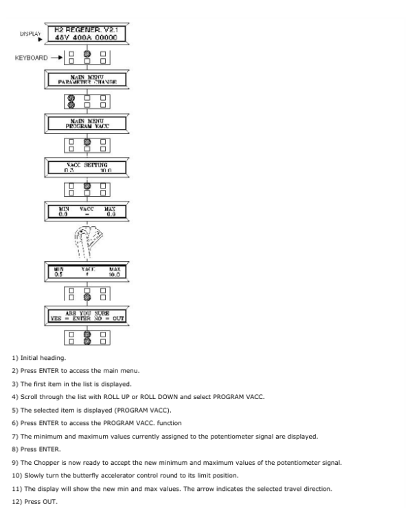
3.13 Main Menu/Program Vacc
3.14 H2 System Configuration Tables
3.15 Table Showing Equivalence Between Parameter Values And Programming Levels
3.16 Calibration Procedure For Initialistaion Of A New Chopper
3.17 Troubleshooting
3.18 Decoding Of Alarms Displayed On Console
Section: Electric Steering
1.0 Electric Steering Board Eps-Dc
1.1 Control Unit
1.2 Logic Board
1.3 Connection Diagram
2.0 Programming Console
2.1 Introduction
2.2 Use Of The Programming Console
2.3 Description Of The Console Menu
2.4 Steering With Tachometric Generator
2.5 Description Of Alarms
2.6 List Of The Main Menu Parameters
2.7 Main Menu: “Alarms” Function
2.8 Configuration Menu/Set Options
Section: Safety Circuits
1.0 Standard Safety Functions
2.0 Optional Safety Functions
3.0 Control Of Safety Functions
3.1 Description Of Safety Control System
3.2 General Description Of The Plc
4.0 Electrical Adjustment Of Proportional Solenoid Valves For Cab Lowering And Mast Lowering
5.0 Programming
5.1 Plc Inputs And Outputs Table
6.0 Removal Of The Plc
7.0 Function And Replacement Of The Backup Batteries
8.0 Problems Related To The Plc Ps3 Power Supply
8.1 Replacing The Fuses Of The Plc Ps3
8.2 Fuse Replacement Procedure
Section: Removal Of Electrical Components
1.0 Removal Of The Hood
2.0 Removal Of The Control Panel
3.0 Replacement Of The Horn And Deadman Microswitch
4.0 Replacement Of Brushes And Drive Motor
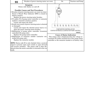
5.0 Replacement Of Pump Motor Brushes
Section: Hydraulic System
1.0 Hydraulic Diagram Without Fork Raising Circuit K1.0L-12
1.1 Hydraulic Diagram With Fork Raising Circuit K1.0L-20
1.2 Hydraulic Diagram With Fork Raising Circuit K0.6M-K1.0M-K1.0H
2.0 Diagram Showing Hydraulic System Components K1.0M
2.1 Diagram Showing Hydraulic System Components K1.0H Duplex
2.2 Diagram Showing Hydraulic System Components K1.0H Triplex
3.0 Solenoid Valves Block
4.0 Diagram Of Cab Raising Cylinder K1.0L
4.1 Diagram Of Fork Raising Cylinder K1.0L
4.2 Cab Raising Cylinder Mod. K1.0L
4.3 Diagram Of Cab Raising Cylinder K0.6M-K1.0M
4.4 Diagram Of Cab Raising Cylinder K0.6M-K1.0M
4.5 Diagram Of Cab Raising Cylinder K1.0H Duplex
4.6 Diagram Of Cab Raising Cylinder K1.0H Triplex
4.7 Diagram Of Fork Raising Cylinder K1.0H Duplex-Triplex
5.0 Removal Of Cab Raising Cylinder Mod.K1.0L
6.0 Replacement Of The Hydraulic Unit
7.0 Removal Of Fork Cylinder – Replacement Of Seals Mod.K1.0L
8.0 Replacement Of Fork Cylinder Seals
8.1 Removal Of Cylinder
9.0 Replacement Of Cab Cylinder Seals
Section: Mechanics
1.0 Components Of The K1.0L Steering System
2.0 Opening The Hoods
3.0 Replacement Of The Drive Wheel K1.0L
3.1 Replacement Of The Drive Wheel K0.6M-K1.0M-K1.0H
4.0 Removal Of The Load Wheels K1.0L
4.1 Removl Of The Load Wheels K0.6M-K1.0M-K1.0H
5.0 Removal Of The Lateral Guard Rails
6.0 Removal Of The Drive Motor K1.0L
6.1 Removal Of The Drive Motor K0.6M-K1.0M
6.2 Removal Of The Drive Motor K1.0H
7.0 Removal Of The Pump Motor K1.0L
8.0 Removal Of The Electric Pump K0.6M-K1.0M
8.1 Removal Of The Electric Pump K1.0H
9.0 Removal Of The Fork Carriage Plate
10.0 Removal Of The Steering Chain/Steering Motor K1.0L
10.1 Removal Of The Steering Chain K0.6M-K1.0M
10.2 Removal Of The Steering Chain K1.0H
11.0 Removal Of The Chain Pulley
12.0 Removal Of The Cab/Masts, Replacement Of Moe Bearings
Section: Reduction Gear
1.0 Reduction Gear Components K1.0L-K0.6M-K1.0M
2.0 Removal Of The Reduction Gear K1.0L
2.1 Removal Of The Reduction Gear K0.6M-K1.0M
3.0 Reduction Gear Components K1.0H
4.0 Removal Of The Reduction Gear K1.0H
5.0 General
5.1 Reduction Gear Components
5.2 Servicing Products
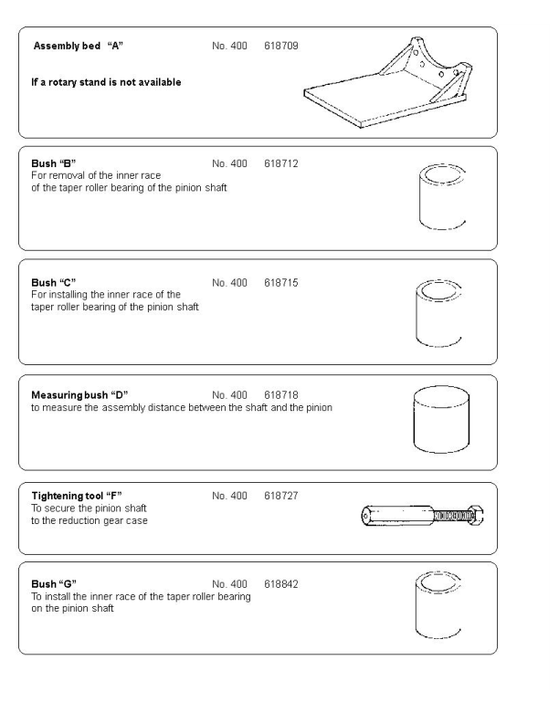
5.3 Standard Instruments And Tools
5.4 Measuring Instruments
6.0 Removal
6.1 Introduction
6.2 Removal And Disassembly Of The Upper Part Of The Reduction Gear Casing
6.3 Removal Of The Reduction Gear Cover
6.4 Removal Of The Crown Wheel And Wheel Axle
6.5 Removal Of The Inner Race Of The Taper Roller Bearing From The Wheel Axle And The Crown Wheel
6.6 Removal Of The Pinion Shaft
6.7 Removal Of The Outer Race Of The Taper Roller Bearing Of The Reduction Gear Casing
6.8 Removal Of The Thread Guard
7.0 Assembly
7.1 Introduction
7.2 Pinion Shaft Assembly Measurements
7.3 Pre-Assembly Of The Reduction Gear Casing
7.4 Pre-Assembly Of The Pinion Shaft
7.5 Assembly Of The Inner Race Of The Crown Wheel Bearing
7.6 Pre-Assembly Of The Pinion Shaft
7.7 Installing The Pinion Shaft In The Reduction Gear Casing
7.8 Measuring The Pinion Shaft Bearing Clearance And Adjustment Of The Preloading
7.9 Installing The Wheel Axle And The Crown Wheel In The Reduction Gear Casing
7.10 Measurement And Adjustment Of The Crown Wheel Run-Out
7.11 Checking The Profile Of The Gear Teeth
7.12 Measuring The Clearance Of The Wheel Axle Bearings And Adjustment Of The Preloading On The Bearings
7.13 Assembly Of The Thread Guard On The Reduction Gear Casing
7.14 Installing The Radial Shaft Seal In The Reduction Gear Casing
7.15 Fitting The Casing Cover
7.16 Upper Part Of The Reduction Gear
8.0 Adjustment Data
8.1 Tightening Torques
9.0 Troubleshooting
10.0 Storage
10.1 Disposal
Section: Braking System
1.0 Components Of The Electromagnetic Brake
2.0 Braking System
2.1 Service Brake
2.2 Emergency And Parking Brake
3.0 Removal Of The Electric Brake
3.1 Adjustment And Putting Into Service
The Service Repair Manual are updated on a regular basis, but may not reflect recent design changes to the product. Updated technical service information may be available from our website.
The Service Repair Manual provide general guidelines for maintenance and service of the A460 Series, Model: K1.0Hand are intended for use by trained and experienced technicians. Failure to properly maintain equipment or to follow instructions contained in the Service Manual could result in damage to the products, personal injury, property damage or death.
• When lifting parts or assemblies, make sure all slings, chains, or cables are correctly fastened, and that the load being lifted is balanced. Make sure the crane, cables, and chains have the capacity to support the weight of the load.
• Do not lift heavy parts by hand, use a lifting mechanism.
• Wear safety glasses.
• DISCONNECT THE BATTERY CONNECTOR before doing any maintenance or repair on electric lift trucks. Disconnect the battery ground cable on internal combustion lift trucks.
• Always use correct blocks to prevent the unit from rolling or falling. See HOW TO PUT THE LIFT TRUCK ON BLOCKS in the Operating Manual or the Periodic Maintenance section.
Caution:
• Always fasten a DO NOT OPERATE tag to the controls of the unit when making repairs, or if the unit needs repairs.
• Be sure to follow the WARNING and CAUTION notes in the instructions.
• Gasoline, Liquid Petroleum Gas (LPG), Compressed Natural Gas (CNG), and Diesel fuel are flammable.
• Be sure to follow the necessary safety precautions when handling these fuels and when working on these fuel systems.
• Batteries generate flammable gas when they are being charged. Keep fire and sparks away from the area. Make sure the area is well ventilated.
Be the first to review “Hyster K1.0H Order Picker A460 Series Repair Manual”
You must be logged in to post a review.


Reviews
There are no reviews yet.