
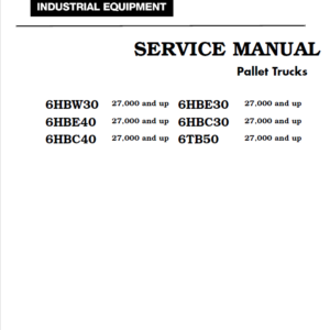
Toyota 8HBW30, 8HBE30, 8HBC30, 8HBE40, 8HBC40, 8TB50 Pallet Trucks Repair Manual
$34.00
Format: PDF
Language: English
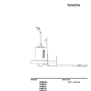
Model Covered: 8HBW30, 8HBE30, 8HBC30, 8HBE40, 8HBC40, 8TB50 (Serial Number 36,001 and up)
- TOYOTA 8HBW30, 8HBE30, 8HBC30, 8HBE40, 8HBC40, 8TB50 Pallet Trucks Repair Manual – 258 Pages
- Description
- Reviews (0)
Description
TOYOTA 8HBW30, 8HBE30, 8HBC30, 8HBE40, 8HBC40, 8TB50 Pallet Trucks Repair Manual
Format: PDF
Language: English
Model Covered: 8HBW30, 8HBE30, 8HBC30, 8HBE40, 8HBC40, 8TB50 (Serial Number 36,001 and up)
- TOYOTA 8HBW30, 8HBE30, 8HBC30, 8HBE40, 8HBC40, 8TB50 Pallet Trucks Repair Manual – 258 Pages
The Toyota Pallet Truck Service Manual is designed with the following objectives in mind:
• Provide technical coverage for expected levels of user expertise
• Anticipate your needs and reduce your decisions regarding maintenance
• Reduce page flipping thru a “one-stop shopping” approach
The two-line running page header at the top of each page tells you:
• Name of the manual (Toyota Pallet Truck Service Manual)
• Current section title
(for example, this page How to Use This Manual)
• Current topic (for example, this page Manual Design)
We suggest you get in the habit of turning to the START page first when you use this manual.
• The START page asks a few questions to guide you to the correct section.
How to Use This Manual explains the manual format and contains the START page.
Safety explains warning and caution notes, general safety rules and safety rules for batteries, static, jacking, and welding.
Systems Overview includes truck specifications and theory of operation information.
Planned Maintenance outlines the recommended schedule of preventive services to keep your truck working most efficiently.
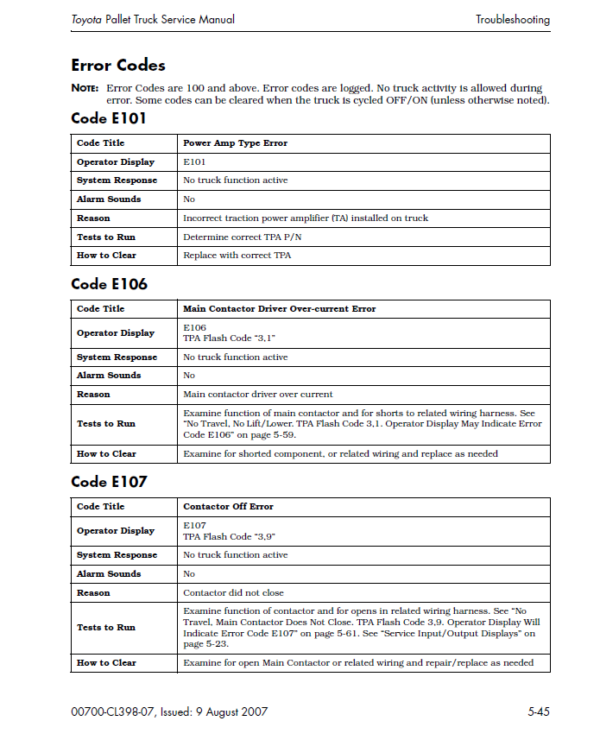
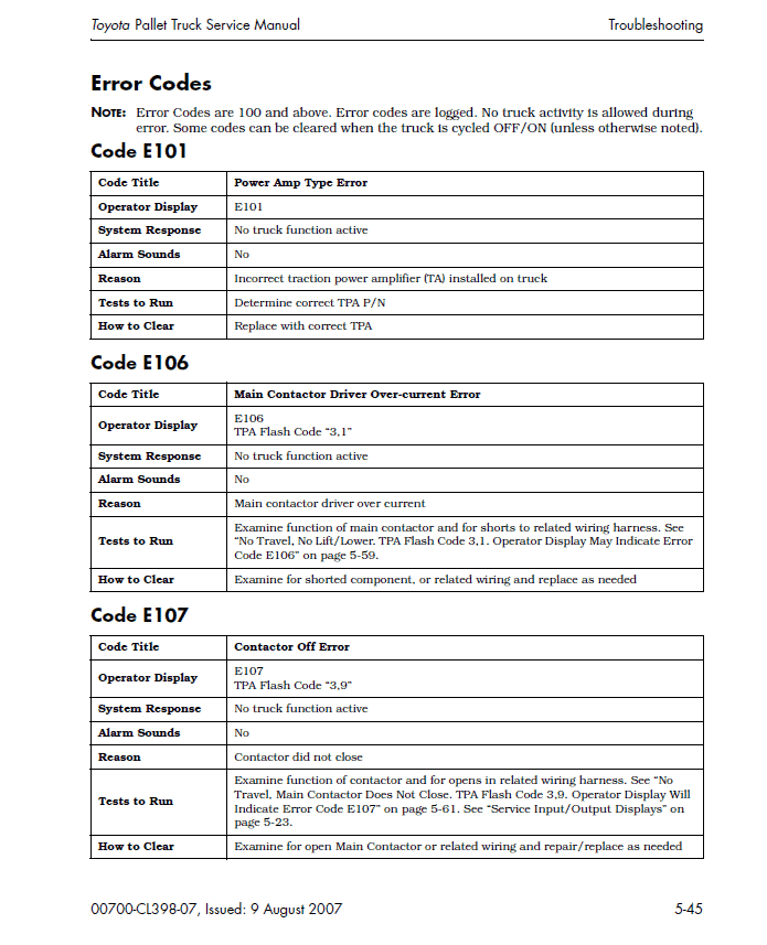
Troubleshooting the 8HBW30, 8HBE30, 8HBC30, 8HBE40, 8HBC40, 8TB50 is a set of fault, caution, and error codes, charts and tables designed to take you from a symptom to a specific sequence of actions in order to isolate a failing component.
• The chart “Traction Power Amplifier Flash Codes” on page 5-27 will guide you thru the flash codes displayed on the LED’s installed on the TA.
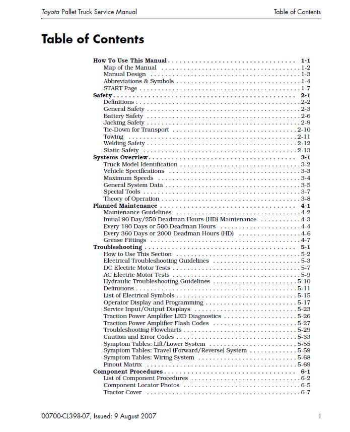
Table of content of the Repair Service Manual
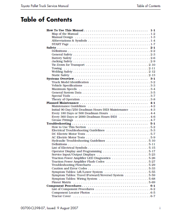
How To Use This Manual . . . . . . . . . . . . . . . . . . . . . . . . . . . . . . . . . 1-1
Map of the Manual . . . . . . . . . . . . . . . . . . . . . . . . . . . . . . . . . . . . . . 1-2
Manual Design . . . . . . . . . . . . . . . . . . . . . . . . . . . . . . . . . . . . . . . . . 1-3
Abbreviations & Symbols . . . . . . . . . . . . . . . . . . . . . . . . . . . . . . . . . . 1-4
START Page . . . . . . . . . . . . . . . . . . . . . . . . . . . . . . . . . . . . . . . . . . . . 1-7
Safety . . . . . . . . . . . . . . . . . . . . . . . . . . . . . . . . . . . . . . . . . . . . . . . 2-1
Definitions . . . . . . . . . . . . . . . . . . . . . . . . . . . . . . . . . . . . . . . . . . . . . 2-2
General Safety . . . . . . . . . . . . . . . . . . . . . . . . . . . . . . . . . . . . . . . . . . 2-3
Battery Safety . . . . . . . . . . . . . . . . . . . . . . . . . . . . . . . . . . . . . . . . . . 2-6
Jacking Safety . . . . . . . . . . . . . . . . . . . . . . . . . . . . . . . . . . . . . . . . . . 2-9
Tie-Down for Transport . . . . . . . . . . . . . . . . . . . . . . . . . . . . . . . . . . 2-10
Towing . . . . . . . . . . . . . . . . . . . . . . . . . . . . . . . . . . . . . . . . . . . . . . 2-11
Welding Safety . . . . . . . . . . . . . . . . . . . . . . . . . . . . . . . . . . . . . . . . . 2-12
Static Safety . . . . . . . . . . . . . . . . . . . . . . . . . . . . . . . . . . . . . . . . . . 2-13
Systems Overview . . . . . . . . . . . . . . . . . . . . . . . . . . . . . . . . . . . . . . 3-1
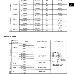
Truck Model Identification . . . . . . . . . . . . . . . . . . . . . . . . . . . . . . . . . 3-2
Vehicle Specifications . . . . . . . . . . . . . . . . . . . . . . . . . . . . . . . . . . . . 3-3
Maximum Speeds . . . . . . . . . . . . . . . . . . . . . . . . . . . . . . . . . . . . . . . 3-4
General System Data . . . . . . . . . . . . . . . . . . . . . . . . . . . . . . . . . . . . . 3-5
Special Tools . . . . . . . . . . . . . . . . . . . . . . . . . . . . . . . . . . . . . . . . . . . 3-7
Theory of Operation . . . . . . . . . . . . . . . . . . . . . . . . . . . . . . . . . . . . . . 3-8
Planned Maintenance . . . . . . . . . . . . . . . . . . . . . . . . . . . . . . . . . . . 4-1
Maintenance Guidelines . . . . . . . . . . . . . . . . . . . . . . . . . . . . . . . . . . 4-2
Initial 90 Day/250 Deadman Hours (HD) Maintenance . . . . . . . . . . . 4-3
Every 180 Days or 500 Deadman Hours . . . . . . . . . . . . . . . . . . . . . . 4-4
Every 360 Days or 2000 Deadman Hours (HD) . . . . . . . . . . . . . . . . . 4-6
Grease Fittings . . . . . . . . . . . . . . . . . . . . . . . . . . . . . . . . . . . . . . . . . 4-7
Troubleshooting . . . . . . . . . . . . . . . . . . . . . . . . . . . . . . . . . . . . . . . 5-1
How to Use This Section . . . . . . . . . . . . . . . . . . . . . . . . . . . . . . . . . . 5-2
Electrical Troubleshooting Guidelines . . . . . . . . . . . . . . . . . . . . . . . . 5-3
DC Electric Motor Tests . . . . . . . . . . . . . . . . . . . . . . . . . . . . . . . . . . . 5-7
AC Electric Motor Tests . . . . . . . . . . . . . . . . . . . . . . . . . . . . . . . . . . . 5-9
Hydraulic Troubleshooting Guidelines . . . . . . . . . . . . . . . . . . . . . . . 5-10
Definitions . . . . . . . . . . . . . . . . . . . . . . . . . . . . . . . . . . . . . . . . . . . . 5-11
List of Electrical Symbols . . . . . . . . . . . . . . . . . . . . . . . . . . . . . . . . . 5-15
Operator Display and Programming . . . . . . . . . . . . . . . . . . . . . . . . . 5-17
Service Input/Output Displays . . . . . . . . . . . . . . . . . . . . . . . . . . . . 5-23
Traction Power Amplifier LED Diagnostics . . . . . . . . . . . . . . . . . . . . 5-26
Traction Power Amplifier Flash Codes . . . . . . . . . . . . . . . . . . . . . . . 5-27
Troubleshooting Flowcharts . . . . . . . . . . . . . . . . . . . . . . . . . . . . . . . 5-29
Caution and Error Codes . . . . . . . . . . . . . . . . . . . . . . . . . . . . . . . . . 5-33
Symptom Tables: Lift/Lower System . . . . . . . . . . . . . . . . . . . . . . . . 5-55
Symptom Tables: Travel (Forward/Reverse) System . . . . . . . . . . . . . 5-59
Symptom Tables: Wiring System . . . . . . . . . . . . . . . . . . . . . . . . . . . 5-68
Pinout Matrix . . . . . . . . . . . . . . . . . . . . . . . . . . . . . . . . . . . . . . . . . 5-69
Component Procedures . . . . . . . . . . . . . . . . . . . . . . . . . . . . . . . . . . 6-1
List of Component Procedures . . . . . . . . . . . . . . . . . . . . . . . . . . . . . . 6-2
Component Locator Photos . . . . . . . . . . . . . . . . . . . . . . . . . . . . . . . . 6-5
Tractor Cover . . . . . . . . . . . . . . . . . . . . . . . . . . . . . . . . . . . . . . . . . . 6-7
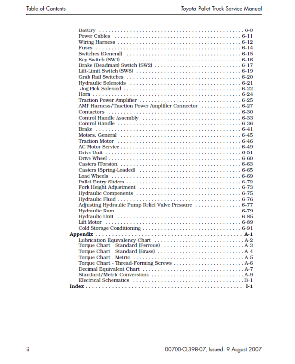
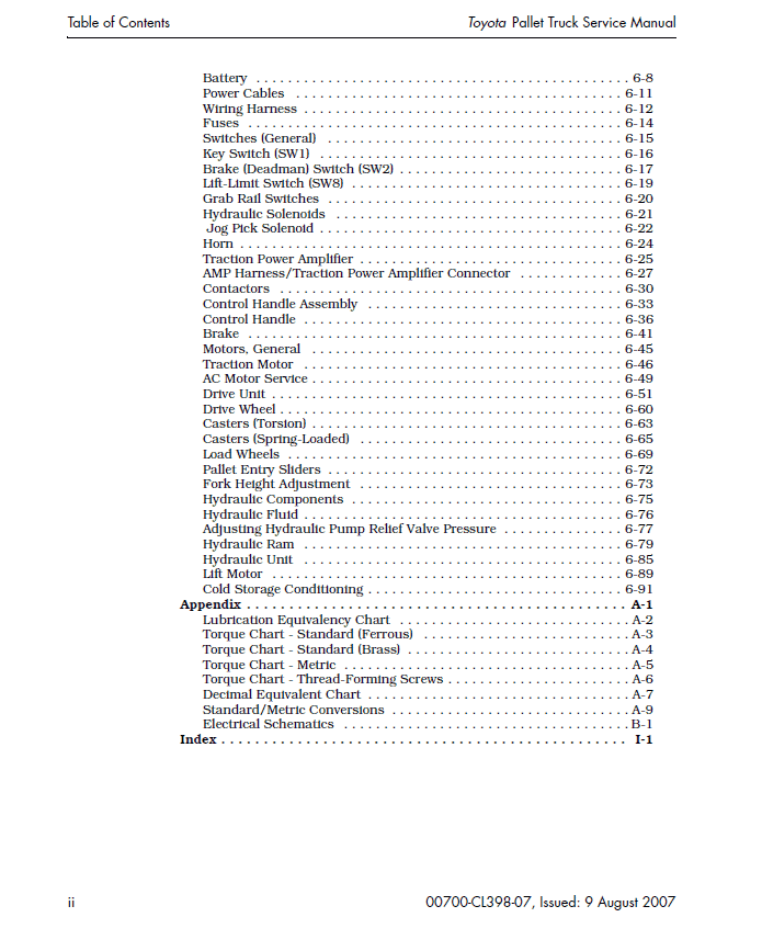
Battery . . . . . . . . . . . . . . . . . . . . . . . . . . . . . . . . . . . . . . . . . . . . . . . 6-8
Power Cables . . . . . . . . . . . . . . . . . . . . . . . . . . . . . . . . . . . . . . . . . 6-11
Wiring Harness . . . . . . . . . . . . . . . . . . . . . . . . . . . . . . . . . . . . . . . . 6-12
Fuses . . . . . . . . . . . . . . . . . . . . . . . . . . . . . . . . . . . . . . . . . . . . . . . 6-14
Switches (General) . . . . . . . . . . . . . . . . . . . . . . . . . . . . . . . . . . . . . 6-15
Key Switch (SW1) . . . . . . . . . . . . . . . . . . . . . . . . . . . . . . . . . . . . . . 6-16
Brake (Deadman) Switch (SW2) . . . . . . . . . . . . . . . . . . . . . . . . . . . . 6-17
Lift-Limit Switch (SW8) . . . . . . . . . . . . . . . . . . . . . . . . . . . . . . . . . . 6-19
Grab Rail Switches . . . . . . . . . . . . . . . . . . . . . . . . . . . . . . . . . . . . . 6-20
Hydraulic Solenoids . . . . . . . . . . . . . . . . . . . . . . . . . . . . . . . . . . . . 6-21
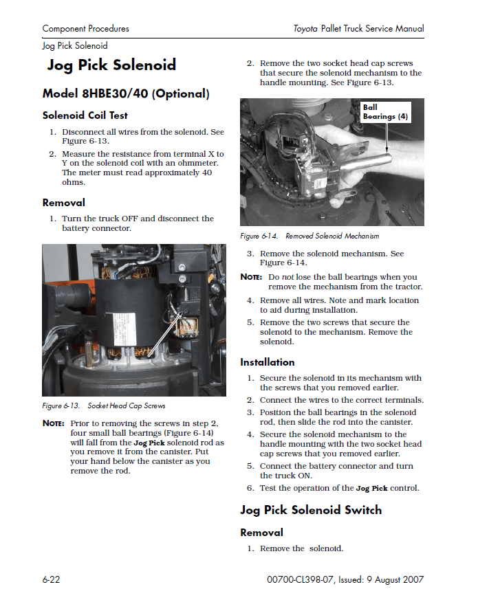
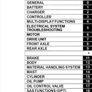
Jog Pick Solenoid . . . . . . . . . . . . . . . . . . . . . . . . . . . . . . . . . . . . . . 6-22
Horn . . . . . . . . . . . . . . . . . . . . . . . . . . . . . . . . . . . . . . . . . . . . . . . . 6-24
Traction Power Amplifier . . . . . . . . . . . . . . . . . . . . . . . . . . . . . . . . . 6-25
AMP Harness/Traction Power Amplifier Connector . . . . . . . . . . . . . 6-27
Contactors . . . . . . . . . . . . . . . . . . . . . . . . . . . . . . . . . . . . . . . . . . . 6-30
Control Handle Assembly . . . . . . . . . . . . . . . . . . . . . . . . . . . . . . . . 6-33
Control Handle . . . . . . . . . . . . . . . . . . . . . . . . . . . . . . . . . . . . . . . . 6-36
Brake . . . . . . . . . . . . . . . . . . . . . . . . . . . . . . . . . . . . . . . . . . . . . . . 6-41
Motors, General . . . . . . . . . . . . . . . . . . . . . . . . . . . . . . . . . . . . . . . 6-45
Traction Motor . . . . . . . . . . . . . . . . . . . . . . . . . . . . . . . . . . . . . . . . 6-46
AC Motor Service . . . . . . . . . . . . . . . . . . . . . . . . . . . . . . . . . . . . . . . 6-49
Drive Unit . . . . . . . . . . . . . . . . . . . . . . . . . . . . . . . . . . . . . . . . . . . . 6-51
Drive Wheel . . . . . . . . . . . . . . . . . . . . . . . . . . . . . . . . . . . . . . . . . . . 6-60
Casters (Torsion) . . . . . . . . . . . . . . . . . . . . . . . . . . . . . . . . . . . . . . . 6-63
Casters (Spring-Loaded) . . . . . . . . . . . . . . . . . . . . . . . . . . . . . . . . . 6-65
Load Wheels . . . . . . . . . . . . . . . . . . . . . . . . . . . . . . . . . . . . . . . . . . 6-69
Pallet Entry Sliders . . . . . . . . . . . . . . . . . . . . . . . . . . . . . . . . . . . . . 6-72
Fork Height Adjustment . . . . . . . . . . . . . . . . . . . . . . . . . . . . . . . . . 6-73
Hydraulic Components . . . . . . . . . . . . . . . . . . . . . . . . . . . . . . . . . . 6-75
Hydraulic Fluid . . . . . . . . . . . . . . . . . . . . . . . . . . . . . . . . . . . . . . . . 6-76
Adjusting Hydraulic Pump Relief Valve Pressure . . . . . . . . . . . . . . . 6-77
Hydraulic Ram . . . . . . . . . . . . . . . . . . . . . . . . . . . . . . . . . . . . . . . . 6-79
Hydraulic Unit . . . . . . . . . . . . . . . . . . . . . . . . . . . . . . . . . . . . . . . . 6-85
Lift Motor . . . . . . . . . . . . . . . . . . . . . . . . . . . . . . . . . . . . . . . . . . . . 6-89
Cold Storage Conditioning . . . . . . . . . . . . . . . . . . . . . . . . . . . . . . . . 6-91
Appendix . . . . . . . . . . . . . . . . . . . . . . . . . . . . . . . . . . . . . . . . . . . . . A-1
Lubrication Equivalency Chart . . . . . . . . . . . . . . . . . . . . . . . . . . . . . A-2
Torque Chart – Standard (Ferrous) . . . . . . . . . . . . . . . . . . . . . . . . . . A-3
Torque Chart – Standard (Brass) . . . . . . . . . . . . . . . . . . . . . . . . . . . . A-4
Torque Chart – Metric . . . . . . . . . . . . . . . . . . . . . . . . . . . . . . . . . . . . A-5
Torque Chart – Thread-Forming Screws . . . . . . . . . . . . . . . . . . . . . . . A-6
Decimal Equivalent Chart . . . . . . . . . . . . . . . . . . . . . . . . . . . . . . . . . A-7
Standard/Metric Conversions . . . . . . . . . . . . . . . . . . . . . . . . . . . . . . A-9
Electrical Schematics . . . . . . . . . . . . . . . . . . . . . . . . . . . . . . . . . . . . B-1
Index . . . . . . . . . . . . . . . . . . . . . . . . . . . . . . . . . . . . . . . . . . . . . . . . I-1
Be the first to review “Toyota 8HBW30, 8HBE30, 8HBC30, 8HBE40, 8HBC40, 8TB50 Pallet Trucks Repair Manual”
You must be logged in to post a review.


Reviews
There are no reviews yet.