 Service Repair Manual")

John Deere 6130, 6230, 6330, 6430, 6530, 6534, 6630 Tractors (EU) Service Repair Manual
$75.00
Language: English
Format: PDF
Publication: TM400419 & TM400519
Region: European
Applicable for the Tractor Model: 6130, 6230, 6330, 6430, 6530, 6534, 6630
- John Deere 6130, 6230, 6330, 6430, 6530, 6534, 6630 Tractors (EU) Service Repair Manual – 1717 Pages
- John Deere Diagnostic Technical Manual – 4178 Pages
- Operators Manual – 240 Pages
- Description
- Reviews (0)
Description
John Deere 6130, 6230, 6330, 6430, 6530, 6534, 6630 Tractors (EU) Service Repair Manual
Language: English
Format: PDF
Publication: TM400419 & TM400519
Region: European
Applicable for the Tractor Model: 6130, 6230, 6330, 6430, 6530, 6534, 6630
- John Deere 6130, 6230, 6330, 6430, 6530, 6534, 6630 Tractors (EU) Service Repair Manual – 1717 Pages
- John Deere Diagnostic Technical Manual – 4178 Pages
- Operators Manual – 240 Pages
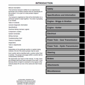
Table of Content of the 6130, 6230, 6330, 6430, 6530, 6534, 6630 Tractors
Repair Manuals
Foreword
Safety
Safety Measures
General Information
Specifications
Tests and Adjustments
Predelivery Inspection
Engine
Removal and Installation of Components
Fuel, Air Intake, Cooling and Exhaust System
Removal and Installation of Components
Speed Control
Fuel System
Air Intake System
Cooling System
Cold-Weather Starting Aids
Exhaust System
Electrical System
Connector Information
Charging Circuit
Starting Circuit
Electrical Components
Electronic Control Units
Removal and Installation of Electronic Control Units
Removal and Installation of Terminating Resistors
SyncroPlus Transmission
Removal and Installation of Components
Transmission Shift Units
Perma Clutch II Module
Gear-Shift Transmission
PowrReverser Transmission
Removal and Installation of Components
Transmission Shift Units
PowrReverser Module
Gear-Shift Transmission
PowrQuad Transmission
Removal and Installation of Components
Transmission Shift Unit
PowrQuad Module
Creeper Transmission
Option Transmission
Range Transmission
Drive Train (without Transmission)
Removal and Installation of Components
U.J. Shaft and Torsion Damper
Front-Wheel Drive Clutch
Differential
Differential – 3D Animation
Hydraulic Pump Drive
Final Drives
Final Drives – 3D Animation
Rear PTO
Front Implement Drive
Steering and Brakes
Hydrostatic Steering
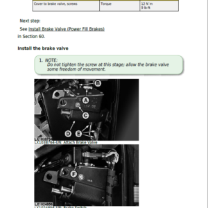
Brake Valve
Rear Brakes
Handbrake
Hydraulic Trailer Brake
Air-Brake System
Hydraulic System
Operator Controls
Oil Filter, Charge Pump and Hydraulic Pump
Valves
Hitch
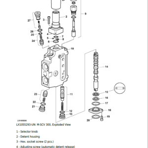
Selective Control Valves and Couplers
Independent Control Valves (ICVs)
Miscellaneous
Removal and Installation of Components
Main Frame
Front Axle
Front Wheels, Rear Wheels and Fenders
Trailer Mounting and Swinging Drawbar
Triple Link Suspension (TLS) of Front-Wheel Drive Axle
Triple Link Suspension (TLS) of Front-Wheel Drive Axle – 3D Animation
Pick-Up Hitch
Operator’s Cab
Removal and Installation of Components
Controls and Instruments
Air Conditioning System
Heating System
Seats
Operator’s Cab
Special Tools
Special Tools (Dealer-Fabricated)
Special Tools (Available as Spare Parts)
Operation and Tests
Foreword
Serial Number Break 2009
General Information
Safety Measures
General References
Diagnostic Trouble Codes
BCU Control Unit
ECU Control Unit
EPC Control Unit
PRC Control Unit
TSC Control Unit
Observable Symptoms
Electronics
Electronic Control Units
SyncroPlus Transmission
PowrReverser Transmission
PowrQuad Transmission
Drive Train (without Transmission)
Steering and Brakes
Hydraulic System
Miscellaneous
Operator’s Cab
System Diagnosis
Electronics
PowrQuad Transmission
Hydraulic System
Engine
General Information
Operational Checks
Tests and Adjustments
Fuel, Air Intake and Cooling Systems
Tests and Adjustments
Fuel System
Air Intake System
Cooling System
Cold-Weather Starting Aids
Electrical System
Starting Motor and Charging Circuit
Fuel Preheater
Electrical Starting Aid
Instrument Unit
Horn
Operator’s Seat and Cigarette Lighter
Lights
Worklights
Radio, Dome Light and Console Light
Air Conditioning and Fan
Windshield Wiper and Washer
Rear Window Wiper and Washer
Beacon Light
3-Terminal Power Outlet Socket (SAE)
3-Terminal Power Outlet Socket (ECE)
Plug for Accessories
BCU Control Unit (Electronic Hitch Control)
BCU Control Unit (Basic Functions)
Signal Socket and Service Socket
7-Terminal Power Outlet Socket (ECE)
7-Terminal Power Outlet Socket (SAE)
TSC Control Unit (Suspension)
CAN BUS Terminating Resistor
Level 16 ECU Control Unit (Electronic Engine Control) for 2-Valve Engine with HPCR
Back-Up Alarm
EPC Control Unit (Transmission Control with PowrQuad Plus Transmission)
PRC Control Unit (Transmission Control with Electrically Actuated PowrReverser Transmission)
SyncroPlus Transmission
Prewiring for GreenStar
Component Information – Connectors and Contacts
Component Information – Connectors (X001 to X249)
Component Information – Connectors (X250 to X499)
Component Information – Connectors (X500 to X749)
Component Information – Connectors (X750 to X999)
Component Information – Connectors (XGND)
Component Information – Wiring Harnesses
Component Information – Electrical Parts/Components
Component Information – Electrical Parts/Components (Actuators)
Component Information – Electrical Parts/Components (Sensors/Switches/Potentiometers)
Component Information – Electrical Parts/Components (Fuses/Relays/Diodes)
Component Information – Electrical Parts/Components (Headlamps/Lights)
Component Information – Electrical Parts/Components (Other)
Component Information – Ground Connections
Component Information – CAN BUS System
Electronic Control Units
Operation and General Information on Diagnostics
Interactive Tests
Interactive Calibrations
Information on How to Reprogram Control Units
Data BUS Systems
BCU Control Unit
ECU Control Unit
EPC Control Unit
PRC Control Unit
TSC Control Unit
SyncroPlus Transmission
Operational Checks
Tests and Adjustments
Operation
PowrReverser Transmission
Operational Checks
Tests and Adjustments
Operation
PowrQuad Transmission
Operational Checks
Tests and Adjustments
Operation
Drive Train (without Transmission)
Operational Checks
Tests and Adjustments
Front-Wheel Drive Clutch
Differential
Final Drives
Rear PTO Options
Steering and Brakes
Introductory Checks
Operational Checks
Tests and Adjustments
Hydrostatic Steering
Brake Valve
Rear Brakes
Handbrake
Hydraulic Trailer Brake
Air-Brake System
Hydraulic System
Operational Checks
Tests and Adjustments
Operation
Oil Filter, Charge Pump and Hydraulic Pump
Hitch
Selective Control Valves (SCVs)
Independent Control Valves (ICVs)
Hydraulic block
Miscellaneous
Operational Checks
Tests and Adjustments
Operation
Operator’s Cab
Operational Checks
Tests and Adjustments
Ventilation/Heating
Air Conditioning System
Special Tools
Special Tools (Dealer-Fabricated)
Special Tools (Available as Spare Parts)
READ THIS MANUAL carefully to learn how to operate and service your Tractors correctly.
Technical manual is divided into two parts: maintenance manual as well as operational principle and test manual. Maintenance manual introduces how to repair machine parts. Operational principle and test manual helps you quickly handle common faults.
The John Deere 6130, 6230, 6330, 6430, 6530, 6534, 6630 Technical manuals are divided in two parts: repair and operation and tests. Repair sections tell how to repair the components. Operation and tests sections help you identify the majority of routine failures quickly.
Information is organized in groups for the various components requiring service instruction. At the beginning of each group are summary listings of all applicable essential tools, service equipment and tools, other materials needed to do the job, service parts kits, specifications, wear tolerances, and torque values.
Technical Manuals are concise guides for specific machines. They are on-the-job guides containing only the vital information needed for diagnosis, analysis, testing, and repair.
Fundamental service information is available from other sources covering basic theory of operation, fundamentals of troubleshooting, general maintenance, and basic type of failures and their causes.
Be the first to review “John Deere 6130, 6230, 6330, 6430, 6530, 6534, 6630 Tractors (EU) Service Repair Manual”
You must be logged in to post a review.
Reviews
There are no reviews yet.