


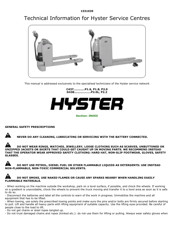

Hyster P2.0L, P2.2 Pallet Truck D438 Series Repair Manual
$25.00
Repair Manual for Hyster D438 Series, Models: P2.0L, P2.2
Format: PDF
English
- Hyster P2.0L, P2.2 Pallet Truck D438 Series Repair Manual: 122 Pages
- Description
- Reviews (0)
Description
Hyster P2.0L, P2.2 Pallet Truck D438 Series Repair Manual
Repair Manual for Hyster D438 Series, Models: P2.0L, P2.2
Format: PDF
English
- Hyster P2.0L, P2.2 Pallet Truck D438 Series Repair Manual: 122 Pages
Hyster D438 Series, Models: P2.0L, P2.2 Manual Table Of Content:
Section: Electrical System
1.00 Presentation Of Models P1.6 – P1.8 – P2.0 – P2.0L – P2.2
1.01 Truck Delivery
1.00 Key To Electrical Diagrams Model P1.6
Electrical Diagrams Model P1.6
– Functional Electrical Diagram Model P1.6 With Battery Charger
– Functional Electrical Diagram Model P1.6 Without Battery Charger
– Wiring Harness Connection Electrical Schematic Model P1.6
– Connectors Electrical Schematic Model P1.6
– Power Cables Connection Electrical Schematic Model P1.6
1.01 Key To Electrical Diagrams Models P1.8 – P2.0 – P2.0L
Electrical Diagrams Models P1.8 – P2.0 – P2.0L
– Functional Electrical Diagram Model P1.8 – P2.0 – P2.0L
– Wiring Harness Connection Electrical Schematic Model P1.8 – P2.0 – P2.0L
– Connectors Electrical Schematic Model P1.8 – P2.0 – P2.0L
– Power Cables Connection Electrical Schematic Model P1.8 – P2.0 – P2.0L
1.02 Key To Electrical Diagrams Model P2.2
Electrical Diagrams Model P2.2
– Functional Electrical Diagram With Horn In External Position Model P2.2
– Wiring Harness Connection Electrical Schematic With Horn External Position Model P2.2
– Functional Electrical Diagram Model P2.2
– Wiring Harness Connection Electrical Schematic Model P2.2
– Connectors Electrical Schematic Model P2.2
– Power Cables Connection Electrical Schematic Model P2.2
2.00 Electrical Components Model P1.6
2.02 Electrical Components Model P1.8
2.04 Electrical Components Models P2.0 – P2.0L
2.06 Electrical Components Model P2.2
2.08 Tiller Control Box Electrical Components
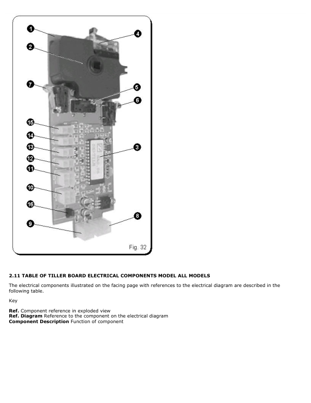
2.10 Tiller Board Electrical Components
2.12 Connection Of Power Cables To The “Mpb” Controller
2.13 Connection Of Power Cables To The “Combi” Controller
3.00 “Mpb” Controller Parameters Table Models P1.6 – P1.8 – P2.0 – P2.0L
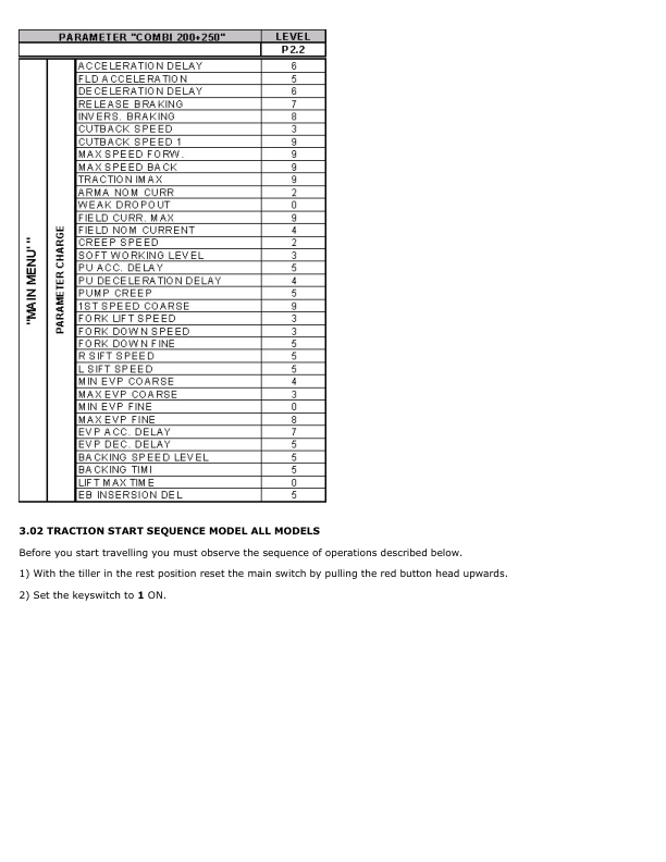
3.01 “Combi” Controller Parameters Table Model P2.2
3.02 Traction Start Sequence
3.03 Procedure For Selecting “Soft, Std, Hard” Performance
3.04 Selection Procedure With The Console
4.00 Disassembly Of The Tiller Control Box
4.02 Traction Potentiometer Signals Acquisition Procedure
4.03 Replacing The Lift / Lower On/Off Pushbutton
5.00 “Mpb” Controller Replacement Procedure
5.01 “Combi” Controller Replacement Procedure
5.02 “Mdi” Replacement Procedure
6.00 Diagnostics, Troubleshooting Guide
– Description Of Alarms And Troubleshooting Guide, Page 1/3 Model All Models
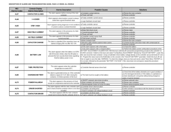
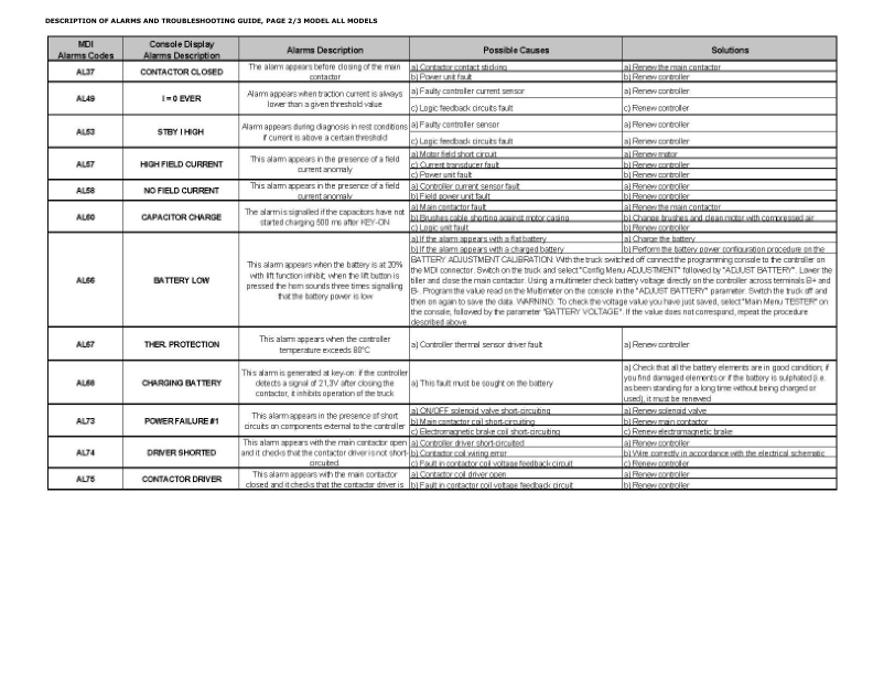
– Description Of Alarms And Troubleshooting Guide, Page 2/3 Model All Models
– Description Of Alarms And Troubleshooting Guide, Page 3/3 Model All Models
Section: Hydraulic System
1.00 Key To Hydraulic System Symbols
1.01 Assembly Method For Female Unions
2.00 Functional Hydraulic Diagram
2.01 Components Of Hydraulic Unit With 1200W Motor
2.02 Components Of Hydraulic Unit With 1000W Motor
2.03 Components Of Hydraulic Unit With 2000W Motor
2.04 Table Of Hydraulic Unit Components (2000W Motor)
2.05 Lift Cylinder Components
2.07 Hydraulic System
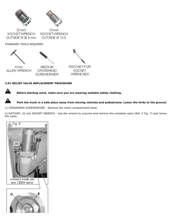
3.00 Relief Valve Replacement Procedure
3.02 Relief Valve Adjustment Procedure
4.00 Cylinder Disassembly Procedure
4.01 Gaskets Replacement Procedure
Section: Linkages
1.00 Linkage Components
1.01 Linkage Components Table
2.00 Tie Rod Removal Procedure
2.01 Rear Lever Replacement Procedure
2.02 Position Of Grease Nipples On The Truck
Section: Mechanics
1.01 Guide Table For The Choice Of Lifting Straps
1.02 Table Of Screw Tightening Torques
2.00 Drive Wheel Replacement Procedure
2.01 Swivel Wheel Assembly Replacement Procedure
2.03 Swivel Wheel Spring Replacement Procedure
2.04 Load Roller Replacement Procedure
3.00 Tiller Gas Spring Replacement Procedure
3.01 Tiller Replacement Procedure
4.00 Traction Motor Replacement Procedure
4.01 800/1000W Traction Motor Components
4.02 Table Of 800/1000W Traction Motor Components
4.03 Bearing Replacement Procedure For 800/1000W Motor
4.06 1500W Traction Motor Components
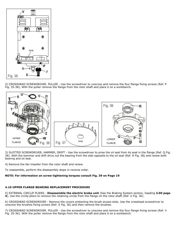
4.08 Bearing Replacement Procedure For 1500W Motor
4.11 Traction Motor Brushes Replacement Procedure
5.00 Hydraulic Power Unit Disassembly Procedure
5.01 1200W Motor Components Tightening Torques Table
5.02 1200W Pump Motor Replacement Procedure
5.05 2000W Motor Components Tightening Torques Table
5.06 2000W Pump Motor Replacement Procedure
5.09 Pump Motor Brushes Replacement Procedure
Section: Reduction Gear
1.00 Reduction Gear Components
2.00 Reduction Gear Removal Procedure
2.03 Maintenance
Section: Braking System
1.00 Electromagnetic Brake Components
2.00 Braking System
3.00 Electromagnetic Brake Removal Procedure
3.01 Inspection And Maintenance
The Service Repair Manual are updated on a regular basis, but may not reflect recent design changes to the product. Updated technical service information may be available from our website.
The Service Repair Manual provide general guidelines for maintenance and service of the D438 Series, Models: P2.0L, P2.2 and are intended for use by trained and experienced technicians. Failure to properly maintain equipment or to follow instructions contained in the Service Manual could result in damage to the products, personal injury, property damage or death.
• When lifting parts or assemblies, make sure all slings, chains, or cables are correctly fastened, and that the load being lifted is balanced. Make sure the crane, cables, and chains have the capacity to support the weight of the load.
• Do not lift heavy parts by hand, use a lifting mechanism.
• Wear safety glasses.
• DISCONNECT THE BATTERY CONNECTOR before doing any maintenance or repair on electric lift trucks. Disconnect the battery ground cable on internal combustion lift trucks.
• Always use correct blocks to prevent the unit from rolling or falling. See HOW TO PUT THE LIFT TRUCK ON BLOCKS in the Operating Manual or the Periodic Maintenance section.
Caution:
• Always fasten a DO NOT OPERATE tag to the controls of the unit when making repairs, or if the unit needs repairs.
• Be sure to follow the WARNING and CAUTION notes in the instructions.
• Gasoline, Liquid Petroleum Gas (LPG), Compressed Natural Gas (CNG), and Diesel fuel are flammable.
• Be sure to follow the necessary safety precautions when handling these fuels and when working on these fuel systems.
• Batteries generate flammable gas when they are being charged. Keep fire and sparks away from the area. Make sure the area is well ventilated.
Be the first to review “Hyster P2.0L, P2.2 Pallet Truck D438 Series Repair Manual”
You must be logged in to post a review.


Reviews
There are no reviews yet.