


Hyster K1.0L Order Picker B457 Series Repair Manual
$30.00
Repair Manual for Hyster B457 Series, B457, Models: K1.0L
Format: PDF
English
- Hyster K1.0L Order Picker B457 Series Repair Manual: 280 Pages
- Description
- Reviews (0)
Description
Hyster K1.0L Order Picker B457 Series Repair Manual
Repair Manual for Hyster B457 Series, B457, Models: K1.0L
Format: PDF
English
- Hyster K1.0L Order Picker B457 Series Repair Manual: 280 Pages
Hyster B457 Series, B457, Models: K1.0L Manual Table Of Content:
Section: Electric System
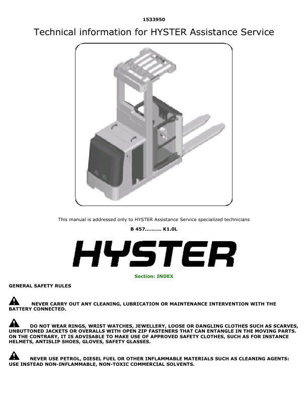
– General Safety Rules
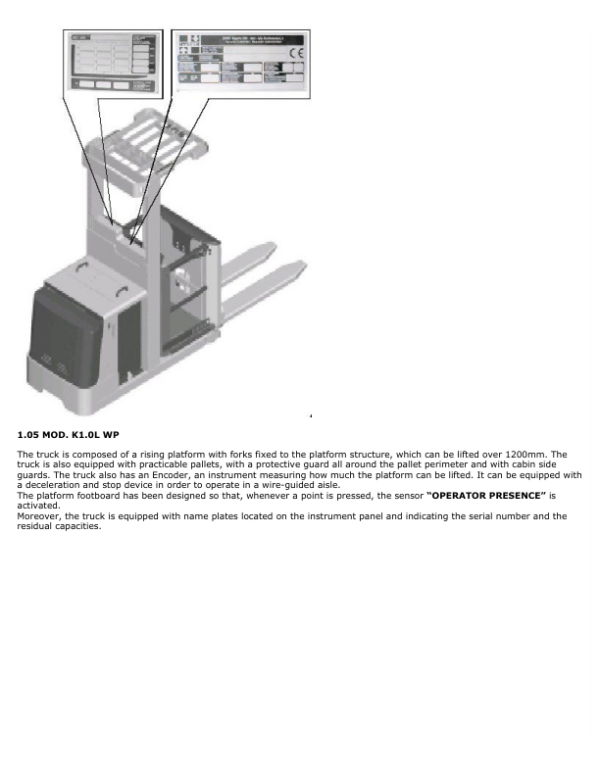
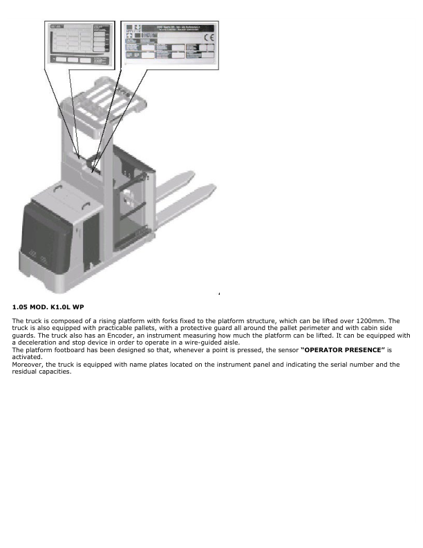
1.00 Truck Description
2.00 Wiring Diagrams – Mod. K1.0L Fp
2.01 Wiring Diagrams – Mod. K1.0L Ff/Wp
2.02 Wiring Diagrams – Mod. K1.0L Sl
2.03 Description Of Sensor And Push Button Functions
3.00 Electric Components – Mod. K1.0L Fp
3.01 Electric Components – Mod. K1.0L Ff/Wp
3.02 Electric Components – Mod. K1.0L Sl
4.00 Table Of The Function Inputs
5.00 Tables Of Module 2 Control €Œcombi€ Parameters
5.01 Tables Of Module 1 Control €Œsicos€ Parameters
5.02 Tables Of Module 6 Control €Œeps-Ac€ Parameters
6.00 Module Calibration Access Procedure
6.01 Module Search Procedure
6.02 Battery Voltage Setting On Control Combi
6.03 Traction Start Sequence
6.04 Speed Reductions
7.00 Module Replacement Procedure
7.01 Module 2 Control Combi Replacement
7.02 Module 6 Control Eps-Ac Replacement
7.03 Module 1 Control Sicos Replacement
7.05 Main Contactor Replacement
7.06 Cooling Fan Replacement
7.07 Steer Stepper Motor Replacement
7.08 Lifting And Braking Joystick Replacement
7.09 Gear Control Potentiometer Card Replacement
7.10 Instrument Panel Push Button Replacement
7.11 Emergency Push Button And Key-Operated Switch Replacement
7.14 Operator Presence Sensor And Warning Horn Replacement
7.15 Lifting Chain Sensor Replacement
7.16 Wheel Centering Sensor Replacement
7.17 Cabin Side Guard Sensor Replacement
8.00 Encoder, Height Preselector
8.01 Encoder Replacement
8.02 Encoder Resetting To Zero Sensor Replacement
9.00 Sicos Display
9.01 Control Component General Description
10. 00 Height Preselector
11.00 Diagnostics
11.01 Module 2 Control Combi
11.02 Module 1 Control Display Sicos
11.03 Module 6 Control Eps-Ac
– Truth Table
– Truth Table
– Electric Components Mod. K1.0L Ff – K1.0L Wp
– Electric Components Mod. K1.0L Fp
– Electric Components Mod. K1.0L Sl
– Functional Wiring Diagram Power And Auxiliaries Mod. K1.0L Ff – K1.0L Wp
– Functional Wiring Diagram Control Combi – Eps-Ac Mod. K1.0L Ff – K1.0L Wp
– Functional Wiring Diagram Control Sicos (Display) Mod. K1.0L Ff – K1.0L Wp
– Motor Compartment Sheath Diagram Mod. K1.0L Ff – K1.0L Wp
– Instrument Panel Sheath Diagram Mod. K1.0L Ff – K1.0L Wp
– Functional Wiring Diagram Power And Auxiliaries Mod. K1.0L Fp
– Functional Wiring Diagram Control Combi – Eps-Ac Mod. K1.0L Fp
– Functional Wiring Diagram Control Sicos (Display) Mod. K1.0L Fp
– Motor Compartment Sheath Diagram Mod. K1.0L Fp
– Instrument Panel Sheath Diagram Mod. K1.0L Fp
– Functional Wiring Diagram Power And Auxiliaries Mod. K1.0L Sl
– Functional Wiring Diagram Control Combi – Eps-Ac Mod. K1.0L Sl
– Functional Wiring Diagram Control Sicos (Display) Mod. K1.0L Sl
– Motor Compartment Sheath Diagram Mod. K1.0L Sl
– Instrument Panel Sheath Diagram Mod. K1.0L Sl
Section: Additional Functions
– Shhet Option 1 = Fan Kit For The Cabin
– Sheet Option 2 = Kit For Reading Desk
– Sheet Option 3 = Safety Tracer Kit
Section: Hydraulic System
1.00 Hydraulic Symbol Legend
1.01 Correct Assembly Method For Female Pipe Fittings
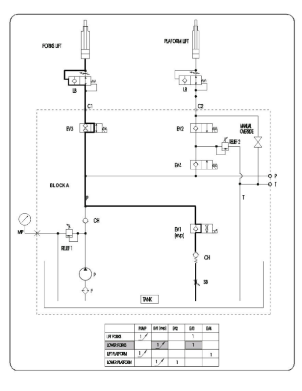
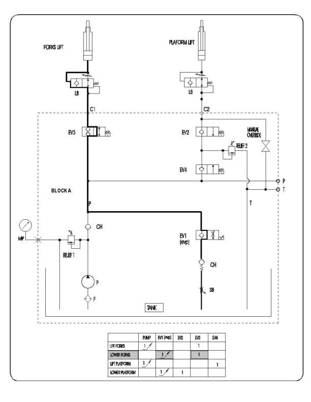
2.00 Functional Hydraulic Diagram – Mod. K1.0L Fp-Ff Wp
2.02 Functional Hydraulic Diagram – Mod. K1.0L Sl
3.00 Hydraulic Power Pack Components – Mod. K1.0L Fp
3.02 Hydraulic Power Pack Components – Mod. K1.0L Ff-Fp
3.04 Hydraulic Power Pack Components – Mod. K1.0L Sl
4.00 Hydraulic System Components – Mod. K1.0L Fp
4.01 Hydraulic System Components – Mod. K1.0L Ff-Wp
4.02 Hydraulic System Components – Mod. K1.0L Sl
4.03 Lifting Cylinder Components – Mod. All Models
4.04 Lifting Cylinder Braking Operation – Mod. All Models
5.00 Valve Adjustment, Replacement – Mod. K1.0L Fp-Ff-Wp
5.04 Valve Adjustment, Replacement – Mod. K1.0L Sl
6.00 Fork Lifting Cylinder Removal – Mod. K1.0L Fp
6.01 Cabin Lifting Cylinder Removal – Mod. K1.0L Ff-Wp
6.02 Fork Lifting Cylinder Removal – Mod. K1.0L Sl
6.03 Cabin Lifting Cylinder Removal – Mod. K1.0L Sl
7.00 Cylinder Gasket Replacement – Mod. All Models
7.01 Hydraulic Brake Valve Replacement – Mod. All Models
8.00 Fork Cylinder Hydraulic Pipe Removal – Mod. K1.0L Fp
8.01 Cabin Cylinder Hydraulic Pipe Removal – Mod. K1.0L Ff-Wp
8.02 Fork Cylinder Hydraulic Pipe Removal – Mod. K1.0L Sl
8.04 Cabin Cylinder Hydraulic Pipe Removal – Mod. K1.0L Sl
Mechanical Section
1.00 Guide Tables For The Choice Of Lifting Straps And Ropes
1.01 Screw Driving Torque Table
2.00 Traction Wheel Removal – Mod. All Models
2.01 Load Wheel Removal – Mod. K1.0L Fp
2.02 Load Wheel Removal – Mod. K1.0L Ff-Sl.Wp
2.03 Traction Motor Removal – Mod. All Models
2.04 Traction Motor Components – Mod. All Models
2.05 Traction Motor Bearing Replacement – Mod. All Models
2.06 Traction Motor Brush Replacement – Mod. All Models
2.07 Traction And Steering Motor Screw Driving Torque Table – Mod. All Models
3.00 Motor Pump Unit Removal – Mod. K1.0L Fp
3.01 Pump Casing Replacement – Mod. K1.0L Fp
3.02 Pump Motor Replacement – Mod. K1.0L Fp
3.03 Pump Motor Brush Replacement – Mod. K1.0L Fp
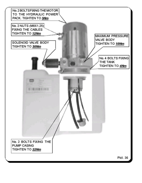
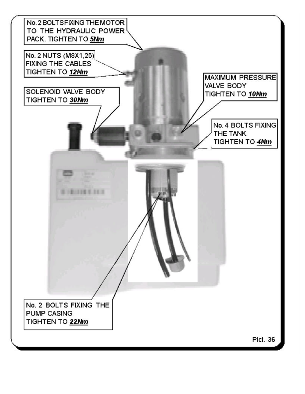
3.04 Motor Pump Unit Screw Driving Torque – Mod. K1.0L Fp
3.05 Motor Pump Unit Removal – Mod. K1.0L Ff-Wp
3.06 Pump Casing Replacement – Mod. K1.0L Ff-Wp
3.07 Pump Motor Removal – Mod. K1.0L Ff-Wp
3.08 Motor Pump Unit Removal – Mod. K1.0L Sl
3.09 Pump Casing Replacement – Mod. K1.0L Sl
3.10 Pump Motor Removal – Mod. K1.0L Sl
3.11 Pump Motor Brush Replacement – Mod. K1.0L Ff-Sl Wp
3.12 Motor Pump Unit Screw Driving Torque – Mod. K1.0L Ff-Wp-Sl
4.00 Lifting Chains – Mod. All Models
4.01 Fork Lifting Chain Removal – Mod. K1.0L Fp
4.02 Platform Lifting Chain Removal – Mod. K1.0L Ff H 1200Mm
4.03 Fork Lifting Chain Removal – Mod. K1.0L Sl
4.04 Platform Lifting Chain Removal – Mod. K1.0L Sl-Wp H 1700Mm
5.00 Platform Side Guard Components – Mod. K1.0L Sl-Wp
5.02 Removal Of The Guard Kit From The Truck – Mod. K1.0L Sl-Wp
5.03 Side Guard Gas Return Spring Replacement – Mod. K1.0L Sl-Wp
5.04 Upper Guard Removal – Mod. K1.0L Sl-Wp
5.05 Intermediate Guard Removal – Mod. K1.0L Sl-Wp
5.06 Lower Guard Removal – Mod. K1.0L Sl-Wp
5.07 Guard Control Bar Removal – Mod. K1.0L Sl-Wp
6.00 Movable Fork Unit Components – Mod. K1.0L Fp-Sl
6.01 Fixed Fork Unit Components – Mod. K1.0L Fp-Sl
6.02 Fixed Or Movable Fork Plate Bearing Replacement – Mod. K1.0L Fp
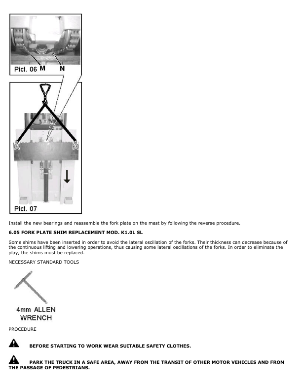
6.04 Movable Or Fixed Fork Plate Bearing Replacement – Mod. K1.0L Sl
7.00 Steering Wheel Pin Bearing Replacement
Section: Reduction Unit
1.00 Reduction Unit Components
1.01 Reduction Unit Component Table
2.00 Reduction Unit Disassembly
2.01 Traction Motor Shaft Oil Seal Replacement
Section: Braking System
Table Of Content:
1.00 Electromagnetic Brake Components
2.00 Braking System
3.00 Electric Brake Coil And Brake Lining Replacement
3.04 Adjustment And Starting
Used Instrument Codes
P/N 2792832 Console (Electric Section)
P/N 1527988 Adapter (Electric Section)
The Service Repair Manual are updated on a regular basis, but may not reflect recent design changes to the product. Updated technical service information may be available from our website.
The Service Repair Manual provide general guidelines for maintenance and service of the B457 Series, B457, Models: K1.0Land are intended for use by trained and experienced technicians. Failure to properly maintain equipment or to follow instructions contained in the Service Manual could result in damage to the products, personal injury, property damage or death.
• When lifting parts or assemblies, make sure all slings, chains, or cables are correctly fastened, and that the load being lifted is balanced. Make sure the crane, cables, and chains have the capacity to support the weight of the load.
• Do not lift heavy parts by hand, use a lifting mechanism.
• Wear safety glasses.
• DISCONNECT THE BATTERY CONNECTOR before doing any maintenance or repair on electric lift trucks. Disconnect the battery ground cable on internal combustion lift trucks.
• Always use correct blocks to prevent the unit from rolling or falling. See HOW TO PUT THE LIFT TRUCK ON BLOCKS in the Operating Manual or the Periodic Maintenance section.
Caution:
• Always fasten a DO NOT OPERATE tag to the controls of the unit when making repairs, or if the unit needs repairs.
• Be sure to follow the WARNING and CAUTION notes in the instructions.
• Gasoline, Liquid Petroleum Gas (LPG), Compressed Natural Gas (CNG), and Diesel fuel are flammable.
• Be sure to follow the necessary safety precautions when handling these fuels and when working on these fuel systems.
• Batteries generate flammable gas when they are being charged. Keep fire and sparks away from the area. Make sure the area is well ventilated.
Be the first to review “Hyster K1.0L Order Picker B457 Series Repair Manual”
You must be logged in to post a review.

Reviews
There are no reviews yet.