
Gehl Z25, Mustang 250Z Compact Excavator Repair Service Manual
$38.00
Language: English
Format: PDF
Applicable for the Gehl Excavator Model Gehl Z25, Mustang 250Z
- Gehl Z25, Mustang 250Z Excavator Repair Service Manual – 576 Pages
- Gehl Z25, Mustang 250Z Excavator Repair Parts Manual – 326 Pages
- Gehl Z25, Mustang 250Z Excavator Repair Parts Manual – 295 Pages
- Description
- Reviews (0)
Description
Key Chapters and Highlights
- General Cautions for Maintenance Work:
- Safety guidelines for disassembly, reassembly, and handling hydraulic components.
- Best practices for installing and maintaining hydraulic hoses and seals.
- Instructions for air release in hydraulic systems.
- Technical Data:
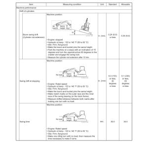
- Machine specifications, working area dimensions, and weight of main components.
- Lifting capacity, hydraulic circuit schematics, and wiring diagrams.
- Recommended fuel, lubrication oils, and periodic inspection schedules.
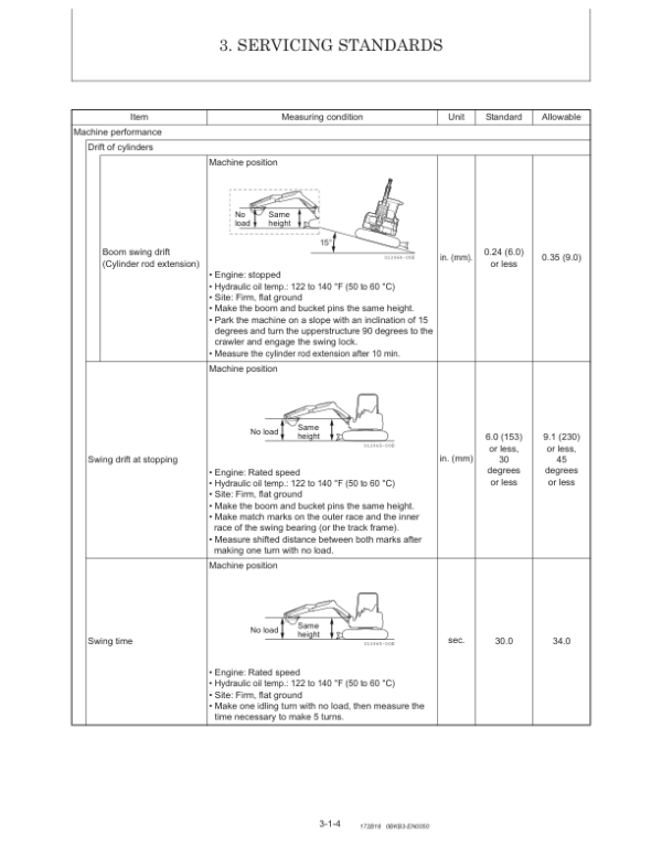
- Service Standards:
- Performance and technical specifications for the engine, undercarriage, controls, and hydraulic equipment.
- Service instructions for front attachments, blade, and bucket teeth.
- Tightening torque values and pressure adjustment details for hydraulic valves.
- Engine:
- Comprehensive servicing guidelines, including valve clearance adjustments, cylinder head maintenance, and cooling system checks.
- Detailed information on the fuel system, lubrication system, starter motor, and alternator.
- Electric wiring diagrams and troubleshooting techniques for engine components.
- Electric System:
- Layout and functions of electrical components, including the LCD monitor and alarm systems.
- Wiring diagrams for engine start/stop and battery charging circuits.
- Error codes and diagnostics for electrical faults.
- Hydraulic System:
- Descriptions of hydraulic circuit operations for components such as the boom, arm, bucket, and travel systems.
- Simultaneous operation scenarios and optional systems like auto deceleration and quick couplers.
- Servicing guidelines for hydraulic pumps, control valves, pilot valves, and swing motors.
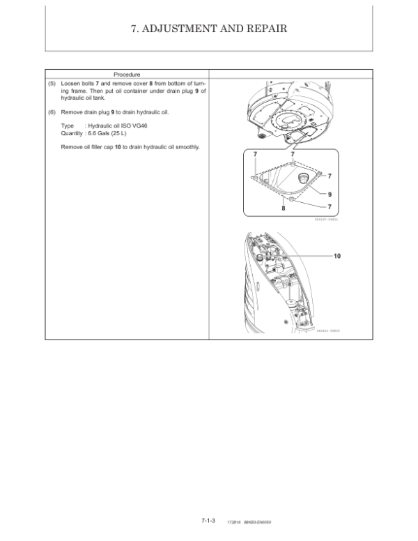
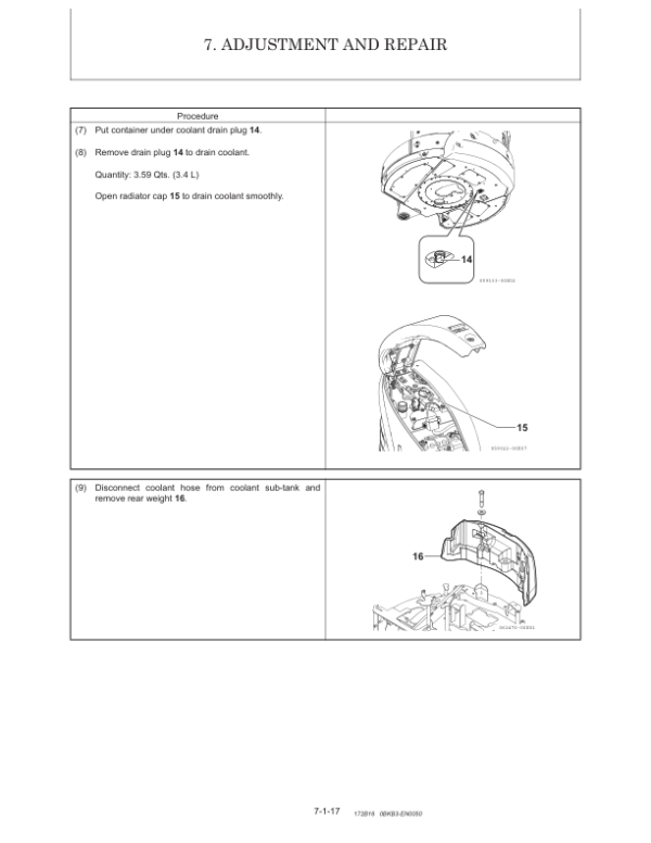
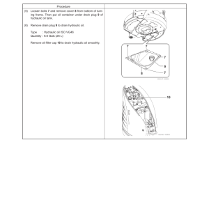
- Adjustment and Repair:
- Instructions for removing and reinstalling key components such as the engine, undercarriage, controls, swing bearing, and hydraulic equipment.
- Procedures for reassembly of tracks, rollers, and cabin components.
- Hydraulic oil tank piping layout and work implement reinstallation details.
- Troubleshooting:
- Quick reference tables and diagnostic guides for resolving common issues.
- Detailed explanations of non-breakdown scenarios, such as bucket release, arm movement irregularities, and thermal shocks in the travel motor.
- Troubleshooting specific hydraulic issues, including oil level fluctuations and operation delays.
Be the first to review “Gehl Z25, Mustang 250Z Compact Excavator Repair Service Manual”
You must be logged in to post a review.


Reviews
There are no reviews yet.