


Gehl GE 503Z, GE 603 Mini Excavator Repair Service Manual
$37.00
Language: English
Format: PDF
Applicable for the Gehl Excavator Model GE 503Z, GE 603 Mini Excavator
- Gehl GE 503Z, GE 603 Mini Excavator Repair Service Manual – 206 Pages
- Gehl GE 503Z, GE 603 Mini Excavator Operators Manual – 132 Pages
- Gehl GE 503Z, GE 603 Mini Excavator Parts Manual – 260 Pages
- Description
- Reviews (0)
Description
Gehl GE 503Z, GE 603 Mini Excavator Repair Service Manual
Language: English
Format: PDF
Applicable for the Gehl Excavator Model GE 503Z, GE 603 Mini Excavator
- Gehl GE 503Z, GE 603 Mini Excavator Repair Service Manual – 206 Pages
- Gehl GE 503Z, GE 603 Mini Excavator Operators Manual – 132 Pages
- Gehl GE 503Z, GE 603 Mini Excavator Parts Manual – 260 Pages
Table of Content of the Gehl GE 503Z, GE 603 Mini Excavator Manual:
Operation …………………………………………………………………………………………………………… 5
General information ……………………………………………………………………………………….. 5
Serial number location ……………………………………………………………………………………. 6
Identification of warnings and hazards ……………………………………………………………… 8
Type decals and component numbers ………………………………………………………………. 9
Machine: overview ……………………………………………………………………………………….. 10
Cab: overview ……………………………………………………………………………………………… 12
Cab: legend ………………………………………………………………………………………………… 13
Instrument panel, switches and indicators: overview (SN AC02893 and up) ………… 14
Instrument panel, switches and indicators: legend (SN AC02893 and up) ……………. 15
Instrument panel, switches and indicators: overview (SN AC02877 and before) …… 16
Instrument panel, switches and indicators: legend (SN AC02877 and before) ……… 17
Engine compartment: overview (SN AH00579 and up) ……………………………………… 18
Engine compartment: overview (SN AH00578 and before) ………………………………… 19
Chassis: overview ………………………………………………………………………………………… 20
Pedal for auxiliary hydraulics/swivelling and rotating the boom …………………………… 20
Tilting the cab ……………………………………………………………………………………………… 21
Heating ………………………………………………………………………………………………………. 22
Specifications ……………………………………………………………………………………………………. 23
Hydraulic system …………………………………………………………………………………………. 25
Undercarriage and swivel unit ……………………………………………………………………….. 26
Dozer blade ………………………………………………………………………………………………… 26
Electrical system ………………………………………………………………………………………….. 27
Sound levels ………………………………………………………………………………………………. 28
Coolant compound table ……………………………………………………………………………….. 28
Model-specific tightening torques …………………………………………………………………… 29
General tightening torques ……………………………………………………………………………. 29
503Z dimensions …………………………………………………………………………………………. 32
Lift capacity table with short dipper arm ………………………………………………………….. 33
Lift capacity table with long dipper arm ……………………………………………………………. 34
Lift capacity table with short dipper arm and counterweight ……………………………….. 35
Lift capacity table with long dipper arm and counterweight ………………………………… 36
Bucket geometry ………………………………………………………………………………………….. 37
Maintenance …………………………………………………………………………………………………….. 39
Fluids and lubricants ……………………………………………………………………………………. 39
Maintenance decal ……………………………………………………………………………………….. 41
Maintenance schedule (overview) ………………………………………………………………….. 43
Introduction …………………………………………………………………………………………………. 47
Fuel system ………………………………………………………………………………………………… 48
Engine lubrication system ……………………………………………………………………………… 52
Cooling system ……………………………………………………………………………………………. 55
Air filter ……………………………………………………………………………………………………….. 58
V-belt …………………………………………………………………………………………………………. 60
Pressure check ……………………………………………………………………………………………. 64
Test report ………………………………………………………………………………………………….. 71
Hydraulic system …………………………………………………………………………………………. 75
Travel drive …………………………………………………………………………………………………. 80
Tracks ………………………………………………………………………………………………………… 81
Lubrication work …………………………………………………………………………………………… 83
Electrical system ………………………………………………………………………………………….. 86
Cab ……………………………………………………………………………………………………………. 90
General maintenance work ……………………………………………………………………………. 91
Long-term storage ……………………………………………………………………………………….. 93
Engine (SN AH00579 and up) ………………………………………………………………………………95
Engine marked 4TNV88-BPNS (SN AH00579 and up): overview ………………………..95
Fuel system ………………………………………………………………………………………………….97
Preparing for cylinder head removal ………………………………………………………………..98
Checking and adjusting valve tip clearance ………………………………………………………98
Removing/Tightening order for cylinder head bolts ……………………………………………99
Checking the injection nozzles ………………………………………………………………………100
Checking the nozzle jet ………………………………………………………………………………..100
Injection timing ……………………………………………………………………………………………101
Adjusting engine speeds ………………………………………………………………………………104
Compression ………………………………………………………………………………………………105
Checking the coolant thermostat …………………………………………………………………..105
Checking the thermal switch …………………………………………………………………………106
Oil pressure switch ………………………………………………………………………………………106
Checking the coolant circuit ………………………………………………………………………….106
Engine (SN AD07125 and before) ………………………………………………………………………107
Engine marked 4TNV88-PNS (SN AD07125 and before): overview …………………..107
Fuel system ………………………………………………………………………………………………..109
Checking and adjusting valve tip clearance …………………………………………………….110
Removing/Tightening order for cylinder head bolts ………………………………………….110
Checking the injection nozzles ………………………………………………………………………111
Checking the nozzle jet ………………………………………………………………………………..112
Injection timing ……………………………………………………………………………………………112
Adjusting engine speeds ………………………………………………………………………………116
Compression ………………………………………………………………………………………………116
Checking the coolant thermostat …………………………………………………………………..116
Checking the thermal switch …………………………………………………………………………117
Oil pressure switch ………………………………………………………………………………………117
Checking the coolant circuit ………………………………………………………………………….118
Engine Troubleshooting ……………………………………………………………………………………119
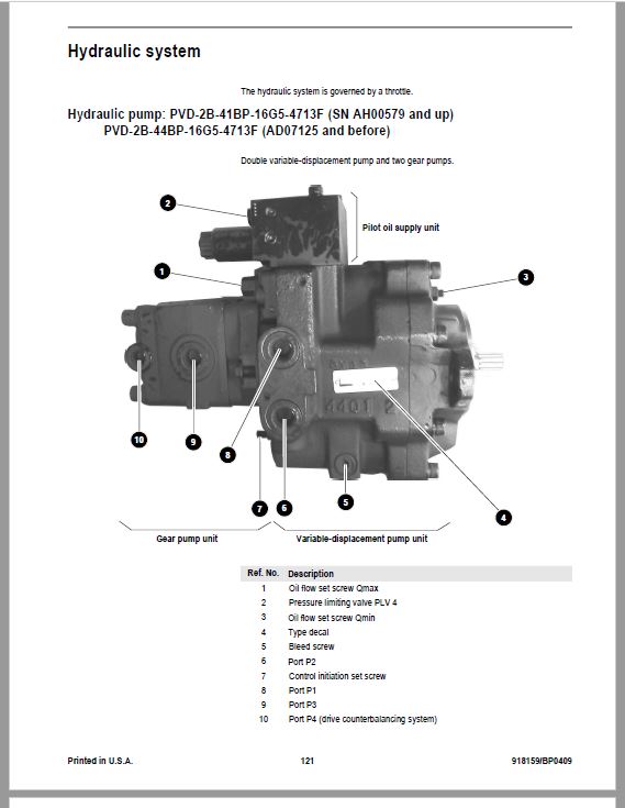
Hydraulic system ………………………………………………………………………………………………121
Hydraulic pump: PVD-2B-41BP-16G5-4713F (SN AH00579 and up)
PVD-2B-44BP-16G5-4713F (AD07125 and before) ……………………………………121
Main valve block …………………………………………………………………………………………125
Drive counterbalancing system ……………………………………………………………………..130
Regeneration – dipper arm section ………………………………………………………………..132
Bucket pre-tension ………………………………………………………………………………………132
Flow rate adjustment for auxiliary hydraulics …………………………………………………..133
Pilot valves …………………………………………………………………………………………………134
Valves ……………………………………………………………………………………………………….140
Travel drive ………………………………………………………………………………………………..143
Swivel unit ………………………………………………………………………………………………….146
Swivel joint …………………………………………………………………………………………………150
Breather filter ……………………………………………………………………………………………..151
Troubleshooting the hydraulic system ……………………………………………………………152
Hydraulics diagram (legend) …………………………………………………………………………153
Hydraulics diagram 503Z ……………………………………………………………………………..155
Options diagram ………………………………………………………………………………………….156
Main valve block diagram 503Z …………………………………………………………………….157
Electrical system ……………………………………………………………………………………………… 159
Ohm’s Law (defines current, voltage and resistance relationship) …………………….. 159
Measuring equipment and methods ……………………………………………………………… 159
Cable color coding ……………………………………………………………………………………… 160
Relays ………………………………………………………………………………………………………. 161
Electrical units ……………………………………………………………………………………………. 161
Fuse box in instrument panel ……………………………………………………………………….. 161
Main fuse box with relays ……………………………………………………………………………. 162
Relays ………………………………………………………………………………………………………. 162
Socket ………………………………………………………………………………………………………. 163
Joystick switch buttons ……………………………………………………………………………….. 163
Instrument panel: overview ………………………………………………………………………….. 164
Switches overview (SN AC02893 and up) ……………………………………………………… 165
Switches overview (SN AC02877 and below) ………………………………………………… 165
Alternator ………………………………………………………………………………………………….. 166
Starter ………………………………………………………………………………………………………. 166
Wiring harness overview ……………………………………………………………………………… 166
Wiring diagram legend (SN AC02890 and up) ……………………………………………….. 167
Wiring diagram (SN AC02890 and up) ………………………………………………………….. 168
Wiring diagram legend (SN AC02889 and before) ………………………………………….. 169
Wiring diagram (SN AC02889 and before) …………………………………………………….. 170
Engine – chassis wiring harness legend ………………………………………………………… 171
Engine – chassis wiring harness …………………………………………………………………… 172
Wiring harness switches (SN AC02890 and up) ……………………………………………… 174
Wiring harness switches legend (SN AC02889 and before) ……………………………… 175
Wiring harness switches (SN AC02889 and before) ……………………………………….. 176
Cab roof wiring harness ………………………………………………………………………………. 177
Armrest wiring harness ……………………………………………………………………………….. 178
Boom working light wiring harness ……………………………………………………………….. 179
Options …………………………………………………………………………………………………………… 181
Air conditioning ………………………………………………………………………………………….. 181
Air-suspension seat ……………………………………………………………………………………. 188
Counterweight ……………………………………………………………………………………………. 188
Long dipper arm …………………………………………………………………………………………. 189
Auxiliary hydraulics connections …………………………………………………………………… 189
Proportional controls …………………………………………………………………………………… 191
Auto-idle feature (SN AH00579 and up) ………………………………………………………… 197
This Service Manual is intended for Gehl GE 503Z, GE 603 Mini Excavator so as to give the owner/operator assistance in preparing, adjusting, maintaining and servicing the machine. More importantly, this manual provides an operating plan for safe and proper use of the machine. Major points of safe operation are
detailed in Chapter 2 – Safety. Read and understand the contents of this manual completely and become familiar with the machine before
attempting to operate it..
Throughout this manual, information is introduced by the word NOTE or IMPORTANT. Be sure to read the message carefully and comply with the message. Following this information will improve operating and maintenance efficiency, help to avoid breakdown and damage and extend the service life of the machine.
Be the first to review “Gehl GE 503Z, GE 603 Mini Excavator Repair Service Manual”
You must be logged in to post a review.


Reviews
There are no reviews yet.