


Gehl GE 383Z Excavator Repair Service Manual
$37.00
Language: English
Format: PDF
Applicable for the Gehl Excavator Model GE 383Z
- Gehl GE 383Z Excavator Repair Service Manual – 174 Pages
- Gehl GE 383Z Excavator Operators Manual – 112 Pages
- Gehl GE 383Z Excavator Repair Parts Manual – 216 Pages
- Description
- Reviews (0)
Description
Gehl GE 383Z Excavator Repair Service Manual
Language: English
Format: PDF
Applicable for the Gehl Excavator Model GE 383Z
- Gehl GE 383Z Excavator Repair Service Manual – 174 Pages
- Gehl GE 383Z Excavator Operators Manual – 112 Pages
- Gehl GE 383Z Excavator Repair Parts Manual – 216 Pages
Table of Content of the Gehl GE 383Z Excavator Manual:
Operation
General Information ……………………………………………………………………………………. 1-1
Serial number location ………………………………………………………………………………… 1-2
Designated uses and exemption from liability ………………………………………………… 1-3
Abbreviations/symbols ………………………………………………………………………………… 1-3
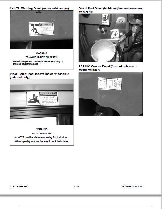
Identification of warnings and dangers ………………………………………………………….. 1-4
Type decals and component numbers …………………………………………………………… 1-5
Machine: overview ……………………………………………………………………………………… 1-6
Cab: overview ……………………………………………………………………………………………. 1-7
Cab: legend ………………………………………………………………………………………………. 1-8
Instrument panel: overview ………………………………………………………………………….. 1-9
Instrument panel: legend …………………………………………………………………………… 1-10
Engine compartment: overview ………………………………………………………………….. 1-11
Chassis: overview …………………………………………………………………………………….. 1-12
Tilting the cab ………………………………………………………………………………………….. 1-13
Cab heat/recirculated air controls ……………………………………………………………….. 1-14
Specifications
Chassis …………………………………………………………………………………………………….. 2-1
Engine ………………………………………………………………………………………………………. 2-1
Fuel injection pump ………………………………………………………………………………. 2-2
Engine capacities …………………………………………………………………………………. 2-2
Engine tightening torques ………………………………………………………………………. 2-2
Hydraulic system ……………………………………………………………………………………….. 2-3
Auxiliary hydraulics oil flow …………………………………………………………………….. 2-3
Undercarriage and swivel unit ……………………………………………………………………… 2-4
Dozer blade ………………………………………………………………………………………………. 2-4
Screwable hose burst valve ……………………………………………………………………. 2-4
Electrical system ………………………………………………………………………………………… 2-5
Fuse box in instrument panel …………………………………………………………………. 2-5
Main fuse box with relays ………………………………………………………………………. 2-5
Relays …………………………………………………………………………………………………. 2-6
Noise levels ………………………………………………………………………………………………. 2-6
Coolant compound table ……………………………………………………………………………… 2-6
Model-specific tightening torques …………………………………………………………………. 2-7
General tightening torques ………………………………………………………………………….. 2-7
Tightening torques for hydraulic screw connections (dry assembly) …………….. 2-7
Tightening torques for high-resistance screw connections ………………………….. 2-9
Dimensions ……………………………………………………………………………………………… 2-10
Standard Long Dipper Arm Load Diagram …………………………………………………… 2-11
Standard Long Dipper Arm with Counterweight Load Diagram ……………………….. 2-12
Optional Short Dipper Arm Load Diagram ……………………………………………………. 2-13
Optional Short Dipper Arm with Counterweight Load Diagram ……………………….. 2-14
Kinematics ………………………………………………………………………………………………. 2-15
Maintenance
Fluids and lubricants ………………………………………………………………………………….. 3-1
Maintenance label ………………………………………………………………………………………. 3-3
Explanation of symbols on the maintenance label ……………………………………… 3-3
Maintenance schedule ………………………………………………………………………………… 3-5
Check, clean or inspect …………………………………………………………………………. 3-5
Fluid and filter changes ………………………………………………………………………….. 3-6
Air conditioning …………………………………………………………………………………….. 3-6
Functional check …………………………………………………………………………………… 3-6
Leakage check ……………………………………………………………………………………… 3-7
Daily lubrication ……………………………………………………………………………………. 3-7
Service packages ……………………………………………………………………………………… 3-10
Introduction ……………………………………………………………………………………………… 3-10
Fuel system ……………………………………………………………………………………………… 3-11
Specific safety instructions …………………………………………………………………… 3-11
Refueling ……………………………………………………………………………………………. 3-11
Stationary fuel pumps ………………………………………………………………………….. 3-12
Bleeding the fuel system ………………………………………………………………………. 3-12
Emptying the fuel tank …………………………………………………………………………. 3-13
Fuel shut-off valve and water separator …………………………………………………. 3-13
Replacing the fuel filter ………………………………………………………………………… 3-14
Engine lubrication system ………………………………………………………………………….. 3-15
Checking the oil level …………………………………………………………………………… 3-15
Adding engine oil ………………………………………………………………………………… 3-16
Changing engine oil and filter ……………………………………………………………….. 3-17
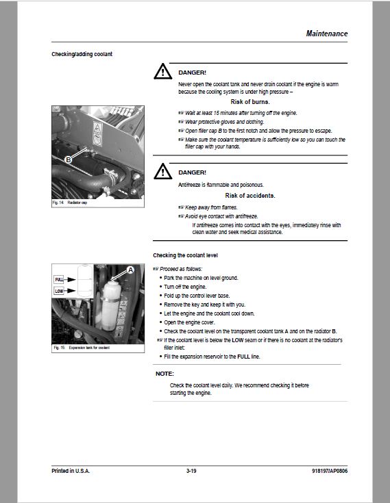
Cooling system ………………………………………………………………………………………… 3-18
Specific safety instructions …………………………………………………………………… 3-18
Checking/adding coolant ……………………………………………………………………… 3-19
Draining coolant ………………………………………………………………………………….. 3-20
Air filter ……………………………………………………………………………………………………. 3-21
Replacing the filter ………………………………………………………………………………. 3-22
Weekly functional check of the dust valve ………………………………………………. 3-23
V-belt ………………………………………………………………………………………………………. 3-24
Checking V-belt tension ……………………………………………………………………….. 3-24
Tightening the V-belt ……………………………………………………………………………. 3-25
Air conditioning V-belt check ………………………………………………………………… 3-26
Tightening the V-belt of the
air conditioning system ………………………………………………………………………… 3-26
Pressure check ………………………………………………………………………………………… 3-27
General ……………………………………………………………………………………………… 3-27
Checking pilot control pressure …………………………………………………………….. 3-27
Variable displacement pump P1 pressure check ……………………………………… 3-28
Variable displacement pump P2 pressure check ……………………………………… 3-29
Pressure check of gear pump P3 ………………………………………………………….. 3-30
Secondary pressure limiting valve of the gear motor ………………………………… 3-31
Measuring ports: overview ……………………………………………………………………. 3-32
Primary pressure limiting valves ……………………………………………………………. 3-32
Test report ……………………………………………………………………………………………….. 3-33
Hydraulic system ………………………………………………………………………………………. 3-37
Specific safety instructions …………………………………………………………………… 3-37
Checking the hydraulic oil level …………………………………………………………….. 3-38
Adding hydraulic oil ……………………………………………………………………………… 3-39
Changing hydraulic oil …………………………………………………………………………. 3-39
Monitoring the hydraulic oil return filter …………………………………………………… 3-40
Checking hydraulic pressure lines …………………………………………………………. 3-41
Checking the final drive oil level and adding oil ……………………………………….. 3-42
Draining oil …………………………………………………………………………………………. 3-42
Tracks …………………………………………………………………………………………………….. 3-43
Checking track tension ………………………………………………………………………… 3-43
Track Tension …………………………………………………………………………………….. 3-44
Lubrication strip ……………………………………………………………………………………….. 3-45
Lubrication strip ………………………………………………………………………………….. 3-45
Attachment maintenance ……………………………………………………………………… 3-45
Electrical system ………………………………………………………………………………………. 3-46
Safety instructions ………………………………………………………………………………. 3-46
Regular service/maintenance ……………………………………………………………….. 3-47
Specific component instructions ……………………………………………………………. 3-47
Alternator …………………………………………………………………………………………… 3-47
Battery ………………………………………………………………………………………………. 3-48
Jump-starting the engine ……………………………………………………………………… 3-49
Cab ………………………………………………………………………………………………………… 3-50
Replacing the inside heater filter …………………………………………………………… 3-50
General maintenance ……………………………………………………………………………….. 3-51
Cleaning ……………………………………………………………………………………………. 3-51
General instructions for all areas …………………………………………………………… 3-51
Inside the cab …………………………………………………………………………………….. 3-52
Seat belt ……………………………………………………………………………………………. 3-52
Exterior of the machine ………………………………………………………………………… 3-52
Engine compartment …………………………………………………………………………… 3-52
Screw connections and attachments ……………………………………………………… 3-52
Pivots and hinges ……………………………………………………………………………….. 3-52
Engine
3TNV88-PNS engine: overview ……………………………………………………………………. 4-1
Fuel system ………………………………………………………………………………………………. 4-3
Checking and adjusting valve tip clearance ……………………………………………………. 4-4
Order for loosening/tightening cylinder head bolts ………………………………………….. 4-5
Checking the injection nozzles …………………………………………………………………….. 4-6
Pressure check …………………………………………………………………………………….. 4-6
Checking the nozzle jet ……………………………………………………………………………….. 4-6
Injection time ……………………………………………………………………………………………… 4-7
Checking injection time ………………………………………………………………………….. 4-7
Setting injection time …………………………………………………………………………….. 4-8
Fuel injection pump replacement …………………………………………………………….. 4-8
Adjusting engine RPM ………………………………………………………………………………. 4-10
Compression ……………………………………………………………………………………………. 4-10
Checking the coolant thermostat ………………………………………………………………… 4-10
Checking the thermal switch ………………………………………………………………………. 4-11
Oil pressure switch …………………………………………………………………………………… 4-11
Checking the coolant circuit ……………………………………………………………………….. 4-12
Engine troubleshooting …………………………………………………………………………….. 4-13
Hydraulic system
Hydraulic pump PVD-2B44BP-16G5-4713F …………………………………………………… 5-1
Pump unit: exploded view ………………………………………………………………………. 5-3
Pilot oil supply unit ………………………………………………………………………………… 5-4
Main valve block ………………………………………………………………………………………… 5-5
Ports …………………………………………………………………………………………………… 5-5
Legend ………………………………………………………………………………………………… 5-6
Main valve block diagram ………………………………………………………………………. 5-7
Pressure limiting valves …………………………………………………………………………. 5-8
Pump assignment …………………………………………………………………………………. 5-9
Drive counterbalancing system …………………………………………………………………… 5-10
Pump assignment for drive counterbalancing …………………………………………. 5-10
Regeneration – dipper arm section ……………………………………………………………… 5-11
Bucket pre-tension ……………………………………………………………………………………. 5-11
Flow rate adjustment of auxiliary hydraulics …………………………………………………. 5-12
Pilot valves ………………………………………………………………………………………………. 5-13
Joystick ……………………………………………………………………………………………… 5-13
Pilot valve (driving) ……………………………………………………………………………… 5-14
Pilot valve for auxiliary hydraulics ………………………………………………………….. 5-16
Valves …………………………………………………………………………………………………….. 5-17
7/2 directional valve (changeover valve) ………………………………………………… 5-17
Changeover valve for SAE/ISO controls …………………………………………………. 5-18
Travel drive – SN AB00855 and after (see page 5-22 for SN up to AB00854) …… 5-19
Function …………………………………………………………………………………………….. 5-20
Travel drive – SN up to AB00854 (see page 5-19 for SN AB00854 and after) …… 5-22
Function …………………………………………………………………………………………….. 5-23
Swivel motor ……………………………………………………………………………………………. 5-25
Parking brake/multidisc brake function …………………………………………………… 5-26
Swivel joint ………………………………………………………………………………………………. 5-29
Sealing ………………………………………………………………………………………………. 5-29
Breather filter …………………………………………………………………………………………… 5-30
Troubleshooting in the hydraulic system ………………………………………………………. 5-31
Hydraulics diagram …………………………………………………………………………………… 5-32
Hydraulics diagram (legend) ………………………………………………………………………. 5-33
Hydraulics diagram …………………………………………………………………………………… 5-35
Main valve block diagram ………………………………………………………………………….. 5-36
Electrical system
Ohm’s Law (current, voltage, resistance); power …………………………………………….. 6-1
Measuring equipment and methods ………………………………………………………………. 6-1
Cable color coding ……………………………………………………………………………………… 6-3
Relays ………………………………………………………………………………………………………. 6-3
Use, mode of function ……………………………………………………………………………. 6-3
Electrical units ……………………………………………………………………………………………. 6-4
Fuse box in instrument panel ……………………………………………………………………….. 6-4
Main fuse box/relays …………………………………………………………………………………… 6-4
Relays ………………………………………………………………………………………………………. 6-4
Socket ………………………………………………………………………………………………………. 6-4
Tip switches on joystick ………………………………………………………………………………. 6-5
Left-hand side joystick …………………………………………………………………………… 6-5
Right-hand side joystick …………………………………………………………………………. 6-5
Alternator ………………………………………………………………………………………………….. 6-6
Starter ………………………………………………………………………………………………………. 6-6
Wiring diagram: legend ……………………………………………………………………………….. 6-8
Wiring diagram …………………………………………………………………………………………… 6-9
Engine wiring harness: legend ……………………………………………………………………. 6-10
Engine wiring harness ……………………………………………………………………………….. 6-11
Cab wiring harness: legend ……………………………………………………………………….. 6-12
Cab wiring harness …………………………………………………………………………………… 6-13
Roof wiring harness ………………………………………………………………………………….. 6-1
This Service Manual is intended for Gehl GE 383Z Excavator so as to give the owner/operator assistance in preparing, adjusting, maintaining and servicing the machine. More importantly, this manual provides an operating plan for safe and proper use of the machine. Major points of safe operation are
detailed in Chapter 2 – Safety. Read and understand the contents of this manual completely and become familiar with the machine before
attempting to operate it..
Throughout this manual, information is introduced by the word NOTE or IMPORTANT. Be sure to read the message carefully and comply with the message. Following this information will improve operating and maintenance efficiency, help to avoid breakdown and damage and extend the service life of the machine.
Be the first to review “Gehl GE 383Z Excavator Repair Service Manual”
You must be logged in to post a review.


Reviews
There are no reviews yet.