
Toyota 6BWC10, 6BWC15, 6BWC20, 6BWS11, 6BWS15, 6BWS20, 6BWR15 Repair Manual
$36.00
Format: PDF
Language: English
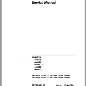
Model Covered: 6BWC10, 6BWC15, 6BWC20, 6BWS11, 6BWS15, 6BWS20, 6BWR15
- Toyota 6BWC10, 6BWC15, 6BWC20, 6BWS11, 6BWS15, 6BWS20, 6BWR15 Repair Manual – 468 Pages
- Wiring Manual – 7 Pages
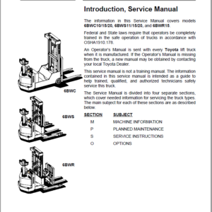
- Description
- Reviews (0)
Description
This repair manual covers inspection, adjustment, and repair procedures for the overhaul of the engine, chassis, and material handling systems of the TOYOTA 6BWC10, 6BWC15, 6BWC20, 6BWS11, 6BWS15, 6BWS20, and 6BWR15 stackers. It includes the latest available information, but design changes may lead to discrepancies between the manual and actual equipment. Updates and modifications are communicated via Toyota Industrial Equipment Parts & Service News.
Highlights of the Manual
1. Safety and Standards
- Safety instructions (general, battery, static, welding).
- Warning symbols and levels, prohibitory and ordinance symbols.
2. Machine Overview
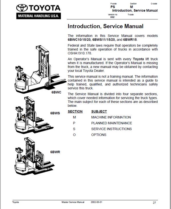
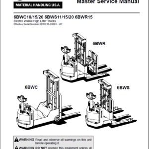
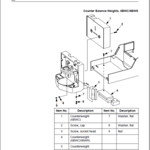
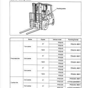
- Truck dimensions, applications, data plates, and main components.
- Presentation of walkie trucks with detailed side views.
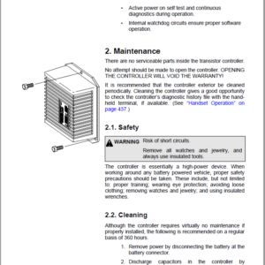
3. Maintenance Guidelines
- Planned maintenance schedules for daily, monthly, and yearly intervals.
- Lubrication charts, oil/grease specifications, and adjustment points.
4. Inspection and Repair
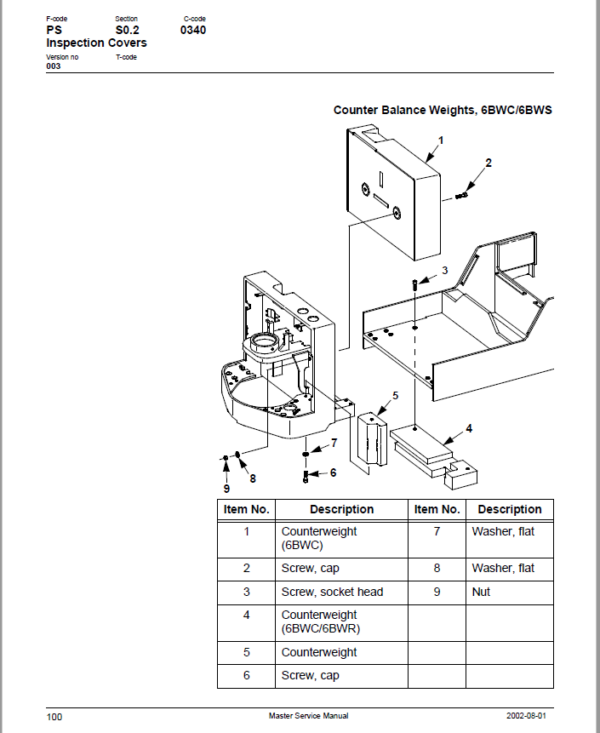
- Frame and chassis inspections, battery rollers, and covers.
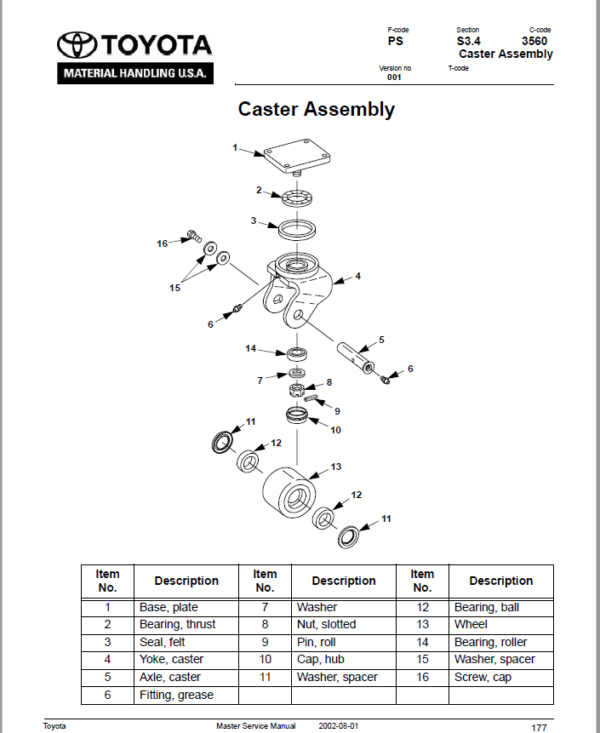
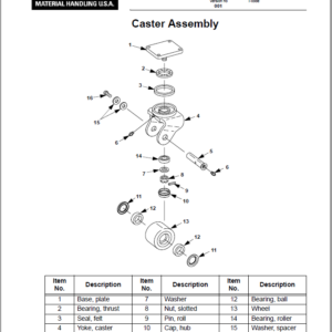
- Drive wheel, support wheel, and caster maintenance and adjustment.
- Load wheel installation and repair procedures.
5. Motors and Transmission
- Maintenance schedules and troubleshooting for pump and drive motors.
- Motor component disassembly, inspection, and reassembly.
- Transmission troubleshooting, repair, and assembly.
6. Braking System
- Parking brake operation and adjustment.
- Brake shoe removal and installation.
7. Hydraulic System
- System functions, schematics, and fluid selection.
- Repair and maintenance of pumps, valves, cylinders, and tanks.
8. Electrical Functions
- Electrical schematics, symbols, and battery maintenance.
- Troubleshooting controllers, hourmeters, and lift interrupts.
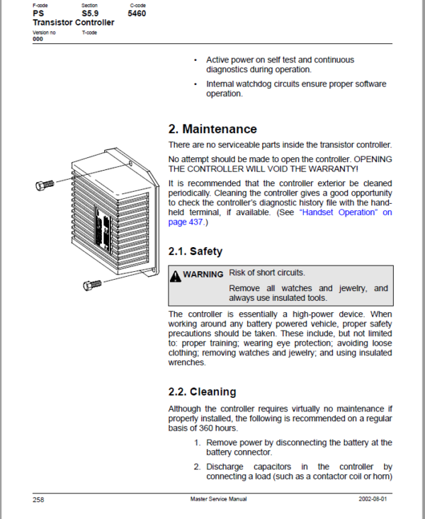
- Overview of transistor controllers and diagnostic tools.
9. Mast and Fork System
- Maintenance, repair, and adjustment of mast stages and lift chains.
- Procedures for sideshifters, reach adjustments, and carriage components.
10. Handset and Diagnostics
- Handset operation, menu navigation, real-time monitoring, and fault reading.
- Programmer setup, parameter changes, and cloning settings.
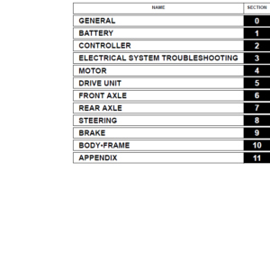
Structure of the Manual
- Each section provides step-by-step procedures for removal, inspection, installation, and assembly.
- Comprehensive troubleshooting charts for diagnosing system issues.
- Technical specifications, conversion charts, and adjustment points are detailed for precise service.
This manual is a complete reference for maintaining and repairing Toyota stackers, ensuring safety, reliability, and optimal performance.
Be the first to review “Toyota 6BWC10, 6BWC15, 6BWC20, 6BWS11, 6BWS15, 6BWS20, 6BWR15 Repair Manual”
You must be logged in to post a review.

Reviews
There are no reviews yet.