
Toyota 6BRU18, 6BRU23, 6BDRU15, 6BSU20, 6BSU25 Electric Reach Repair Manual
$36.00
Format: PDF
Language: English
Model Covered: 6BRU18, 6BRU23, 6BDRU15, 6BSU20, 6BSU25
- Toyota 6BRU18, 6BRU23, 6BDRU15, 6BSU20, 6BSU25 Electric Reach Repair Manual – 514 Pages
- Parts Catalog Manual – 228 Pages
- Wiring Diagram Manual – 6 Pages
- Description
- Reviews (0)
Description
Toyota 6BRU18, 6BRU23, 6BDRU15, 6BSU20, 6BSU25 Electric Reach Repair Manual
Format: PDF
Language: English
Model Covered: 6BRU18, 6BRU23, 6BDRU15, 6BSU20, 6BSU25
- Toyota 6BRU18, 6BRU23, 6BDRU15, 6BSU20, 6BSU25 Electric Reach Repair Manual – 514 Pages
- Parts Catalog Manual – 228 Pages
- Wiring Diagram Manual – 6 Pages
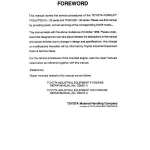
This manual covers the inspection, adjustment and repair procedures mainly for the overhaul of the engine, chassis and material handling system of the TOYOTA 6BRU18, 6BRU23, 6BDRU15, 6BSU20, 6BSU25 Electric Reach.
This repair manual contains the latest information available. Please under-stand that disagreement can take place between the descriptions in the manual and actual vehicles due to change in design and specifications. Any change or modifications thereafter will be informed by Toyota Industrial Equipment Parts & Service News.
For the service procedures of the mounted engine, read the repair manuals listed below as reference together with this manual.
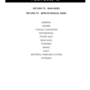
Table of content of the TOYOTA 6BRU18, 6BRU23, 6BDRU15, 6BSU20, 6BSU25 Electric Reach Manual
Map of the Manual ……………………………….. 1-2
Manual Design ………………………………….. 1-3
Page Revision Record . . . . . . . . . . . . . . . . . . . . . . . . . . . . . . . . . . . . . 1-5
Table of Contents . . . . . . . . . . . . . . . . . . . . . . . . . . . . . . . . . . . . . . . 1-9
STARTPage ……………………………………. 1-13
Safety …………………………………….. 2-1
Definitions …………………………………….. 2-2
Generalsafe ty …………………………………… 2-3
Battery Safety . . . . . . . . . . . . . . . . . . . . . . . . . . . . . . . . . . . . . . . . . . 2-7
Staticsafet y …………………………………… 2-11
JackingSafet y ………………………………….. 2-13
Tie-down for Transport ……………………………. 2-14
Welding Safety …………………………………. 2-15
Systems Oveniew . . . . . . . . . . . . . . . . . . . . . . . . . . . . . . . . . . . 3-1
Vehicle Specifications . . . . . . . . . . . . . . . . . . . . . . . . . . . . . . . . . . . . 3-2
General System Data ………………………………. 3-3
Brake ………………………………………… 3-4
Steering . . . . . . . . . . . . . . . . . . . . . . . . . . . . . . . . . . . . . . . . . . . . . . 3-5
Lift/Lower System ………………………………… 3-6
Auxiliary System . . . . . . . . . . . . . . . . . . . . . . . . . . . . . . . . . . . . . . . . 3-7
Traction System …………………………………. 3-9
Modes of Operation ………………………………. 3-10
Scheduled Maintenance ………………………… 4-1
Maintenance Guidelines ……………………………. 4-2
Daily or Every Eight (8) Operating Hours …………………. 4-3
Monthly or Every 200 Operating Hours . . . . . . . . . . . . . . . . . . . . . . . 4-4
Semi-annually or Every 1000 Operating Hours. . . . . . . . . . . . . . . . . . 4 -6
Annually or Every 2000 Operating Hours . . . . . . . . . . . . . . . . . . . . . . 4 -7
Lubricants . . . . . . . . . . . . . . . . . . . . . . . . . . . . . . . . . . . . . . . . . . . . . 4-8
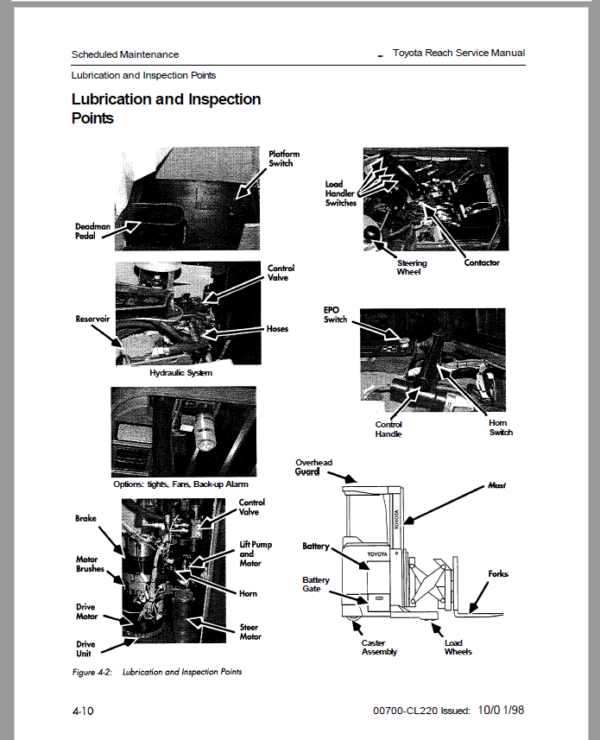
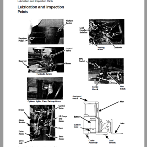
Lubrication and Inspection Points . . . . . . . . . . . . . . . . . . . . . . . . . . 4-10
Troubleshooting . . . . . . . . . . . . . . . . . . . . . . . . . . . . . . . . . . . . 5-1
How to Use This Chapter . . . . . . . . . . . . . . . . . . . . . . . . . . . . . . . . . . 5-2
Electrical Troubleshooting Guidelines . . . . . . . . . . . . . . . . . . . . . . . . 5-3
Shorts to Frame Test . . . . . . . . . . . . . . . . . . . . . . . . . . . . . . . . . . . . . 5-4
Hydraulic Troubleshooting Guidelines . . . . . . . . . . . . . . . . . . . . . . . 5-10
Definitions …………………………………….. 5-11
Electrical Connector Locator Chart. . . . . . . . . . . . . . . . . . . . . . . . . . 5-13
Electrical Connector Locator Photos . . . . . . . . . . . . . . . . . . . . . . . . . 5-15
Troubleshooting Flowcharts. . . . . . . . . . . . . . . . . . . . . . . . . . . . . . . 5-19
Electrical Codes and Tests . . . . . . . . . . . . . . . . . . . . . . . . . . . . 6-1
Passwords ……………………………………… 6-3
Disable the Brush Wear Warning . . . . . . . . . . . . . . . . . . . . . . . . . . . . 6-4
Start the Hour Meter . . . . . . . . . . . . . . . . . . . . . . . . . . . . . . . . . . . . . 6 -5
Self-diagnosis Mode . . . . . . . . . . . . . . . . . . . . . . . . . . . . . . . . . . . . . . 6 -6
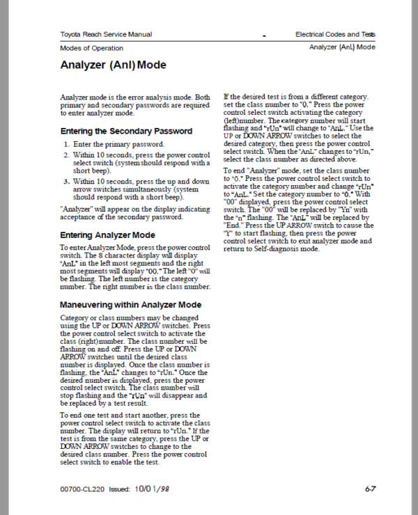
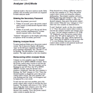
Analyzer (Ax&) Mode . . . . . . . . . . . . . . . . . . . . . . . . . . . . . . . . . . . . . 6-7
Calibrate (Calibrte) Mode . . . . . . . . . . . . . . . . . . . . . . . . . . . . . . . . . . 6 -8
Configure (Configur) Mode . . . . . . . . . . . . . . . . . . . . . . . . . . . . . . . . 6-10
Tuning (Tuning) Mode . . . . . . . . . . . . . . . . . . . . . . . . . . . . . . . . . . . 6-11
Code Summary Tables . . . . . . . . . . . . . . . . . . . . . . . . . . . . . . . . . . . 6-14
Analog Tests (Category 1, Class 2) . . . . . . . . . . . . . . . . . . . . . . . . . . 6-84
Component Procedures . . . . . . . . . . . . . . . . . . . . . . . . . . . . . . . 7-1
Theory of Operation . . . . . . . . . . . . . . . . . . . . . . . . . . . . . . . . . 8-1
Electrical Functions . . . . . . . . . . . . . . . . . . . . . . . . . . . . . . . . . . . . . . 8-2
Brakingsystem ………………………………….. 8-4
Steering System . . . . . . . . . . . . . . . . . . . . . . . . . . . . . . . . . . . . . . . . . 8-5
Traction System . . . . . . . . . . . . . . . . . . . . . . . . . . . . . . . . . . . . . . . . 8-6
Lift/Lower System . . . . . . . . . . . . . . . . . . . . . . . . . . . . . . . . . . . . . . . 8-9
Auxiliary Hydraulic Functions . . . . . . . . . . . . . . . . . . . . . . . . . . . . . 8-1 1
Indicators and Switches . . . . . . . . . . . . . . . . . . . . . . . . . . . . . . . . . 8-1 8
Appendix . . . . . . . . . . . . . . . . . . . . . . . . . . . . . . . . . . . . . . . . . 9-1
Lubrication Equivalency Chart . . . . . . . . . . . . . . . . . . . . . . . . . . . . . 9-2
Torque Chart . Standard (Ferrous) . . . . . . . . . . . . . . . . . . . . . . . . . . 9-5
Torque Chart . Standard (Brass). . . . . . . . . . . . . . . . . . . . . . . . . . . . 9-7
Torque Chart . Metric . . . . . . . . . . . . . . . . . . . . . . . . . . . . . . . . . . . . 9-8
Decimal Equivalent Chart . . . . . . . . . . . . . . . . . . . . . . . . . . . . . . . . . 9-9
Standard/Metric Conversions . . . . . . . . . . . . . . . . . . . . . . . . . . . . . 9-1 1
Electrical Schematic Legend . . . . . . . . . . . . . . . . . . . . . . . . . . . . . . 9-1 3
Electrical Schematic . . . . . . . . . . . . . . . . . . . . . . . . . . . . . . . . . . . . 9-1 4
Hydraulic Schematic . . . . . . . . . . . . . . . . . . . . . . . . . . . . . . . . . . . . 9- 16
Hydraulic Schematic . . . . . . . . . . . . . . . . . . . . . . . . . . . . . . . . . . . . 9- 17
Hydraulic Schematic . . . . . . . . . . . . . . . . . . . . . . . . . . . . . . . . . . . . 9-1 8
Index ……………………………………. 10-1
How to Use This Manual explains the manual format and design and contains the Table of Contents and START page. Safety explains warning and caution notes, general safety rules and safety rules for batteries, static, jacking, and welding. Systems Overview includes truck specifications and functional overview of the major systems.
Scheduled Maintenance outlines the recommended schedule of preventive services to keep your truck working most efficiently.
Troubleshooting is a set of “decision-tree” charts designed to take you from a symptom to a specific sequence of tests in order to isolate a failing component. The START TROUBLESHOOTING chart (on page 5-20) will guide you to the individual troubleshooting symptom chart you need.
Once you’re familiar with the symptoms listed, you may instead simply find the symptom chart from the List of Troubleshooting Charts (page 5- 19). Manual Design Index lists subjects alphabetically. When you complete a troubleshooting procedure, be sure to follow the steps in End of Troubleshooting Chart END- 1 (page 5-23).
Electrical Codes and Tests contains detailed description of the software modes of operation and information about electrical error codes and diagnostic tests under the control of the system firmware.
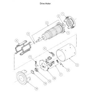
Component Procedures gives step-by-step procedures for testing, removal, installation, and adjustment of individual truck components. Components are listed in an order which considers: Frequency of attention Physical attachment (e.g., brake must be removed before drive motor) Functional relation (e.g., carriage and mast components are grouped together) To find a component procedure, you may use one of three methods: Look up the component name in the List of Component Procedures (page 7- 1). Find the component in the Component Locators (page 7-3). Look up the component name in the maintenance manual Index (10- 1).
Theory of Operation gives detailed theory of operation information for all major systems. Appendix contains reference information such as torque values, lubricants, and schematics
Be the first to review “Toyota 6BRU18, 6BRU23, 6BDRU15, 6BSU20, 6BSU25 Electric Reach Repair Manual”
You must be logged in to post a review.


Reviews
There are no reviews yet.