
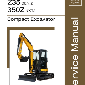
Gehl Z35 Gen 2, Mustang 350Z Nxt 2 Compact Excavator Repair Service Manual
$40.00
Language: English
Format: PDF
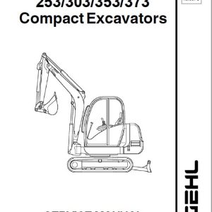
Applicable for the Gehl Excavator Model Gehl Z35 Gen 2, Mustang 350Z Nxt 2
- Gehl Z35 Gen 2, Mustang 350Z Nxt 2 Excavator Repair Service Manual – 730 Pages
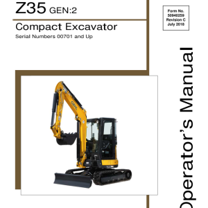
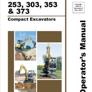
- Gehl Z35 Gen 2, Mustang 350Z Nxt 2 Excavator Operators Manual – 318 Pages
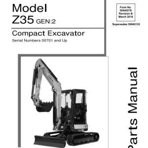
- Gehl Z35 Gen 2, Mustang 350Z Nxt 2 Excavator Parts Manual – 424 Pages
- Description
- Reviews (0)
Description
Key Chapters and Highlights
- General Cautions for Maintenance Work:
- Safety guidelines for maintenance tasks, disassembly, reassembly, and handling of hydraulic components.
- Best practices for hydraulic hose installation, seal handling, and air release procedures.
- Technical Data:
- Detailed specifications, working area dimensions, and weight lists of main parts.
- Hydraulic and electrical schematics, wiring diagrams, and recommended fuel, lubricants, and grease.
- Lifting capacity and periodic inspection schedules.
- Service Standards:
- Performance standards for the machine, engine, undercarriage, and hydraulic equipment.
- Tightening torque values for various components and pressure adjustment settings for hydraulic valves.
- Specifications for rubber crawlers, blade moving devices, and bucket teeth.
- Engine:
- Comprehensive servicing instructions for the engine, including valve clearance adjustments and EGR system maintenance.
- Detailed procedures for fuel system components, cooling systems, lubrication systems, starter motors, alternators, and the electronic control system.
- Wiring diagrams and troubleshooting methods for engine-related components.
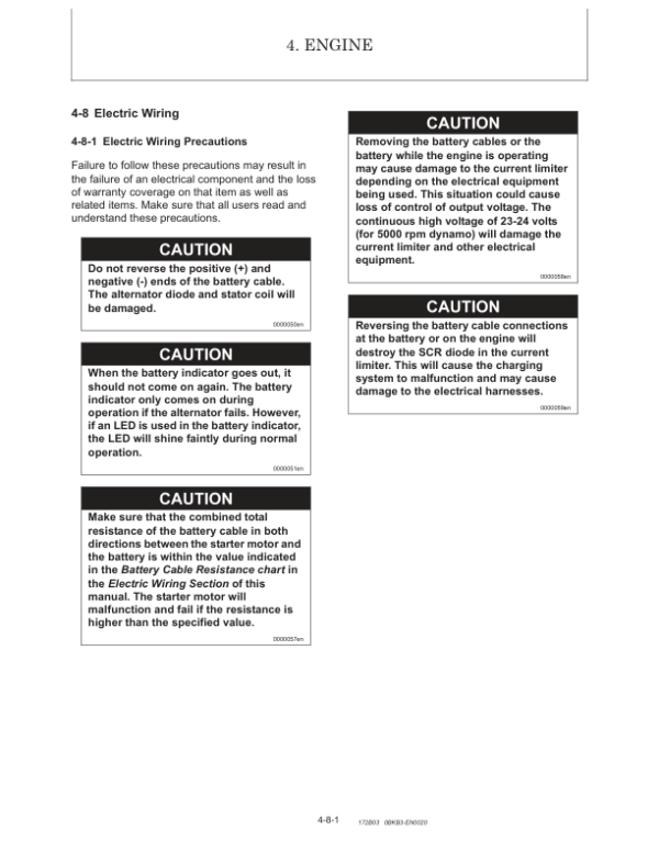
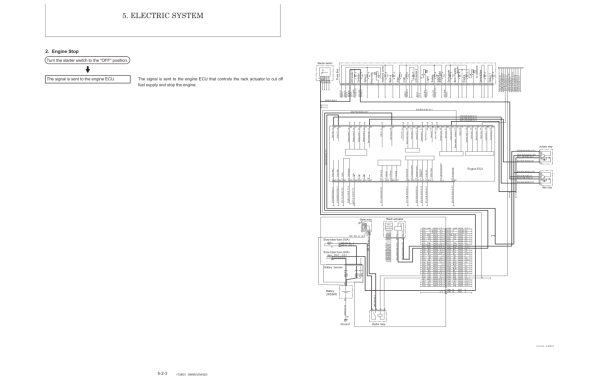
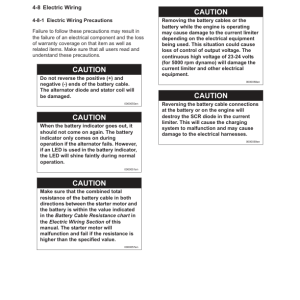
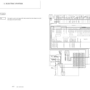
- Electric System:
- Overview of the electrical equipment, LCD monitor, and alarm systems.
- Description of electronic control systems for start/stop, auto deceleration, Eco mode, and engine speed/output control.
- Error codes and diagnostic tools for troubleshooting.
- Hydraulic System:
- Detailed explanations of hydraulic circuit operations, including boom, arm, bucket, swing, and blade systems.
- Instructions for handling simultaneous operations, quick couplers, and hydraulic P.T.O. (Power Take-Off).
- Maintenance and repair procedures for hydraulic pumps, control valves, pilot valves, swing motors, and travel motors.
- Adjustment and Repair:
- Instructions for the removal, reinstallation, and servicing of key components such as the engine, undercarriage, controls, swing bearings, and cabin.
- Hydraulic system repairs, including disassembly and reassembly of hydraulic cylinders, swivel joints, and oil tanks.
- Work implement adjustments, including quick coupler and air conditioner servicing.
- Troubleshooting:
- Diagnostic guides for non-breakdown issues, such as bucket release, arm movement irregularities, and thermal shocks.
- Quick reference tables for troubleshooting common problems, including hydraulic system oil fluctuations and travel speed delays.
Be the first to review “Gehl Z35 Gen 2, Mustang 350Z Nxt 2 Compact Excavator Repair Service Manual”
You must be logged in to post a review.

Reviews
There are no reviews yet.