


Gehl GE 753Z Excavator Repair Service Manual
$37.00
Language: English
Format: PDF
Applicable for the Gehl Excavator Model GE 753Z
- Gehl GE 753Z Excavator Repair Service Manual – 184 Pages
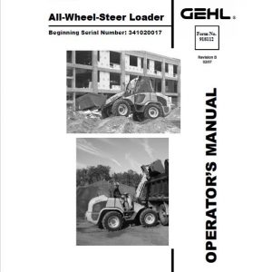
- Gehl GE 753Z Excavator Operators Manual – 136 Pages
- Gehl GE 753Z Excavator Parts Manual – 238 Pages
- Description
- Reviews (0)
Description
Gehl GE 753Z Excavator Repair Service Manual
Language: English
Format: PDF
Applicable for the Gehl Excavator Model GE 753Z
- Gehl GE 753Z Excavator Repair Service Manual – 184 Pages
- Gehl GE 753Z Excavator Operators Manual – 136 Pages
- Gehl GE 753Z Excavator Parts Manual – 238 Pages
Table of Content of the Gehl GE 753Z Excavator Manual:
Operation
Important Information about this Service Manual ……………………………………………. 1-1
Abbreviations/Symbols ……………………………………………………………………………….. 1-1
Identification of Warnings and Hazards …………………………………………………………. 1-2
Designated Use and Exemption from Liability ………………………………………………… 1-2
Type Decals and Component Numbers …………………………………………………………. 1-3
Serial Number Location ………………………………………………………………………………. 1-3
Engine Number ………………………………………………………………………………………….. 1-3
Hydraulic Pump Identification Number ………………………………………………………….. 1-4
Main Valve Block Identification Number ………………………………………………………… 1-4
Travel Drive Identification Number ……………………………………………………………….. 1-4
Swivel Unit Identification Number …………………………………………………………………. 1-4
Machine Overview ……………………………………………………………………………………… 1-5
Cab Overview ……………………………………………………………………………………………. 1-6
Cab Legend ………………………………………………………………………………………………. 1-7
Instrument Panel Overview ………………………………………………………………………….. 1-8
Instrument Panel Legend …………………………………………………………………………….. 1-9
Engine Compartment Overview ………………………………………………………………….. 1-10
Chassis Overview …………………………………………………………………………………….. 1-11
Tilting the Cab ………………………………………………………………………………………….. 1-12
Tilting the Cab Down ………………………………………………………………………………… 1-13
SAE Operating Controls (Standard) ……………………………………………………………. 1-14
ISO Operating Controls (Selectable) …………………………………………………………… 1-15
Boom Slew/Auxiliary Hydraulics Pedal ………………………………………………………… 1-16
Dozer Blade …………………………………………………………………………………………….. 1-16
Throttle Lever …………………………………………………………………………………………… 1-17
Operator’s Seat Adjustments ……………………………………………………………………… 1-18
Ventilation ……………………………………………………………………………………………….. 1-20
Windshield ………………………………………………………………………………………………. 1-20
Cab Door Latch Release …………………………………………………………………………… 1-21
Interior Light …………………………………………………………………………………………….. 1-21
Tool Kit and Cab Jack Handle ……………………………………………………………………. 1-21
Cab Heat Control ……………………………………………………………………………………… 1-22
Recirculated Air Mode ………………………………………………………………………………. 1-22
Hydraulics/Swiveling and Boom Rotation Pedal Adjustment …………………………… 1-23
Specifications
Chassis …………………………………………………………………………………………………….. 2-1
Engine ………………………………………………………………………………………………………. 2-1
Hydraulic System ……………………………………………………………………………………….. 2-3
Undercarriage and Swivel Unit …………………………………………………………………….. 2-4
Dozer Blade ………………………………………………………………………………………………. 2-4
Electrical System ……………………………………………………………………………………….. 2-5
Sound Levels ……………………………………………………………………………………………. 2-7
Coolant Compound Table ……………………………………………………………………………. 2-7
Model-Specific Tightening Torques ………………………………………………………………. 2-7
General Specifications ………………………………………………………………………………… 2-8
Extended Dipper Arm Lift Capacities …………………………………………………………… 2-10
Lift Capacities with Counterweight ………………………………………………………………. 2-11
Lift Capacities with Extended Dipper Arm and Counterweight ………………………… 2-12
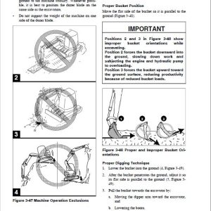
Bucket Geometry ……………………………………………………………………………………… 2-13
Maintenance
General Information Care and Servicing ………………………………………………………… 3-1
Care and Servicing …………………………………………………………………………………….. 3-1
Maintenance Safety ……………………………………………………………………………………. 3-2
Fluids and Lubricants …………………………………………………………………………………. 3-3
Maintenance Decal Symbols ……………………………………………………………………….. 3-5
Maintenance Decal …………………………………………………………………………………….. 3-6
Maintenance Schedule ……………………………………………………………………………….. 3-7
General Maintenance ………………………………………………………………………………… 3-10
Lubrication ………………………………………………………………………………………………. 3-12
Fuel System …………………………………………………………………………………………….. 3-13
Fuel Filter ………………………………………………………………………………………………… 3-14
Fuel Shut-Off Valve, Fuel Prefilter and Water Separator ………………………………… 3-14
Purging Air from the Fuel System ……………………………………………………………….. 3-15
Engine Lubrication System ………………………………………………………………………… 3-16
Changing Engine Oil and Filter …………………………………………………………………… 3-16
Coolant System ………………………………………………………………………………………… 3-18
Checking Coolant Level …………………………………………………………………………….. 3-18
Air Cleaner Service …………………………………………………………………………………… 3-19
Dust Valve Functional Check ……………………………………………………………………… 3-20
Checking and Adjusting V-Belt Tension ……………………………………………………….. 3-21
Checking and Adjusting Air Conditioning V-Belt Tension ……………………………….. 3-22
Pressure Check ……………………………………………………………………………………….. 3-23
Test Report ……………………………………………………………………………………………… 3-29
Hydraulic System ……………………………………………………………………………………… 3-32
Checking Hydraulic Oil Level ……………………………………………………………………… 3-32
Changing Hyraulic Oil ……………………………………………………………………………….. 3-34
Hydraulic Cooling System ………………………………………………………………………….. 3-34
Adding Hydraulic Oil …………………………………………………………………………………. 3-35
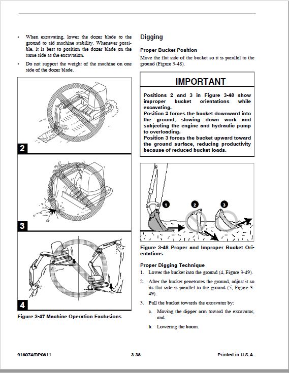
Specific Safety Instructions ………………………………………………………………………… 3-36
Track System …………………………………………………………………………………………… 3-37
Changing Final Drive Oil ……………………………………………………………………………. 3-37
Electrical System ……………………………………………………………………………………… 3-40
Using a Booster Battery (Jump-Starting) ……………………………………………………… 3-41
Cab Heater Filter ………………………………………………………………………………………. 3-43
Engine
Engine Overview ………………………………………………………………………………………… 4-1
Fuel System ………………………………………………………………………………………………. 4-3
Removing the Cylinder Head Cover ……………………………………………………………… 4-4
Checking and Adjusting Valve Tip Clearance …………………………………………………. 4-4
Cylinder Head Bolt Tightening Order …………………………………………………………….. 4-6
Checking the Injection Nozzles …………………………………………………………………….. 4-6
Checking the Nozzle Jet ……………………………………………………………………………… 4-7
Injection Timing ………………………………………………………………………………………….. 4-8
Adjusting Engine RPM ………………………………………………………………………………… 4-9
Checking Compression ……………………………………………………………………………….. 4-9
Checking the Coolant Thermostat ………………………………………………………………. 4-10
Checking the Thermal Switch …………………………………………………………………….. 4-10
Oil Pressure Switch …………………………………………………………………………………… 4-11
Checking the Coolant Circuit ……………………………………………………………………… 4-11
Engine Troubleshooting …………………………………………………………………………….. 4-12
Hydraulic System
Hydraulic Pump …………………………………………………………………………………………. 5-1
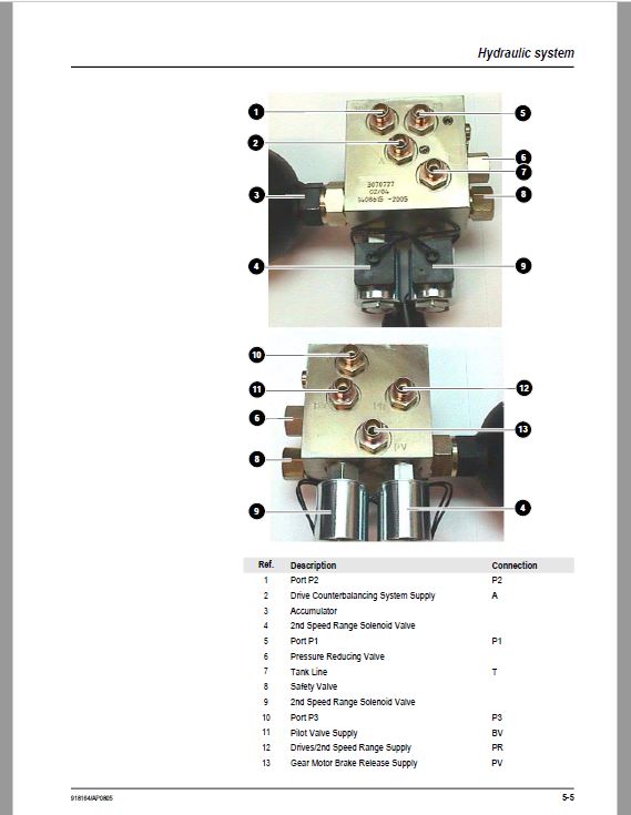
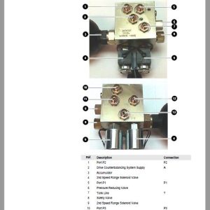
Main Valve Block ……………………………………………………………………………………….. 5-6
Drive Counterbalancing System …………………………………………………………………. 5-11
Regeneration — Dipper Arm Section ………………………………………………………….. 5-13
Bucket Pre-Tension ………………………………………………………………………………….. 5-13
Boom Raise …………………………………………………………………………………………….. 5-14
Check Valve (Load Retaining Valve) …………………………………………………………… 5-15
Raising the Boom …………………………………………………………………………………….. 5-15
Lowering the Boom …………………………………………………………………………………… 5-15
Dipper Arm Cylinder, Extend ……………………………………………………………………… 5-16
Secondary Pressure Limiting Valves for the Auxiliary Hydraulics (Option) ……….. 5-17
Pilot Valves ……………………………………………………………………………………………… 5-18
Valves …………………………………………………………………………………………………….. 5-23
Travel Drive …………………………………………………………………………………………….. 5-28
Travel Drive …………………………………………………………………………………………….. 5-30
Swivel Unit ………………………………………………………………………………………………. 5-34
Swivel Joint ……………………………………………………………………………………………… 5-39
Breather Filter ………………………………………………………………………………………….. 5-40
Troubleshooting the Hydraulic System ………………………………………………………… 5-41
Main Valve Block Diagram …………………………………………………………………………. 5-43
Hydraulic Diagram) …………………………………………………………………………………… 5-44
Hydraulic Diagram ……………………………………………………………………………………. 5-45
Main Valve Block Diagram with 3rd Control Circuit ……………………………………….. 5-46
Electrical System
Ohm’s Law (Current, Voltage, Resistance); Power …………………………………………. 6-1
Measuring Equipment, Measuring Methods …………………………………………………… 6-1
Cable Color Coding ……………………………………………………………………………………. 6-2
Relays ………………………………………………………………………………………………………. 6-3
Electric Units ……………………………………………………………………………………………… 6-3
Fuse Box in Instrument Panel ………………………………………………………………………. 6-3
Main Fuse Box with Relays …………………………………………………………………………. 6-4
Relays ………………………………………………………………………………………………………. 6-4
Lubrication Block Accessory Power Socket ……………………………………………………. 6-5
Joystick Tip Switches ………………………………………………………………………………….. 6-5
Instrument Panel Overview ………………………………………………………………………….. 6-6
Switch Overview ………………………………………………………………………………………… 6-7
Alternator ………………………………………………………………………………………………….. 6-8
Starter ………………………………………………………………………………………………………. 6-8
Boom Working Light Wiring Harness …………………………………………………………….. 6-9
Wiring Diagram Legend …………………………………………………………………………….. 6-10
Wiring Diagram ………………………………………………………………………………………… 6-11
Engine — Chassis Wiring Harness ……………………………………………………………… 6-12
Engine — Chassis Wiring Harness ……………………………………………………………… 6-13
Wiring Harness: Switches ………………………………………………………………………….. 6-14
Wiring Harness: Switches ………………………………………………………………………….. 6-15
Cab Roof Wiring Harness ………………………………………………………………………….. 6-16
Armrest Wiring Harness …………………………………………………………………………….. 6-17
Options
Air Conditioning ………………………………………………………………………………………….. 7-1
Counterweight ……………………………………………………………………………………………. 7-9
Extended Dipper Arm ………………………………………………………………………………….. 7-9
Control Circuit Hydraulic Coupling Connections ……………………………………………. 7-10
3rd Control Circuit Connections ………………………………………………………………….. 7-10
Auxiliary Hydraulics Connections ………………………………………………………………… 7-11
Automatic Idling Speed ……………………………………………………………………………… 7-12
This Service Manual is intended for Gehl GE 753Z Excavator so as to give the owner/operator assistance in preparing, adjusting, maintaining and servicing the machine. More importantly, this manual provides an operating plan for safe and proper use of the machine. Major points of safe operation are
detailed in Chapter 2 – Safety. Read and understand the contents of this manual completely and become familiar with the machine before
attempting to operate it..
Throughout this manual, information is introduced by the word NOTE or IMPORTANT. Be sure to read the message carefully and comply with the message. Following this information will improve operating and maintenance efficiency, help to avoid breakdown and damage and extend the service life of the machine.
Be the first to review “Gehl GE 753Z Excavator Repair Service Manual”
You must be logged in to post a review.


Reviews
There are no reviews yet.