

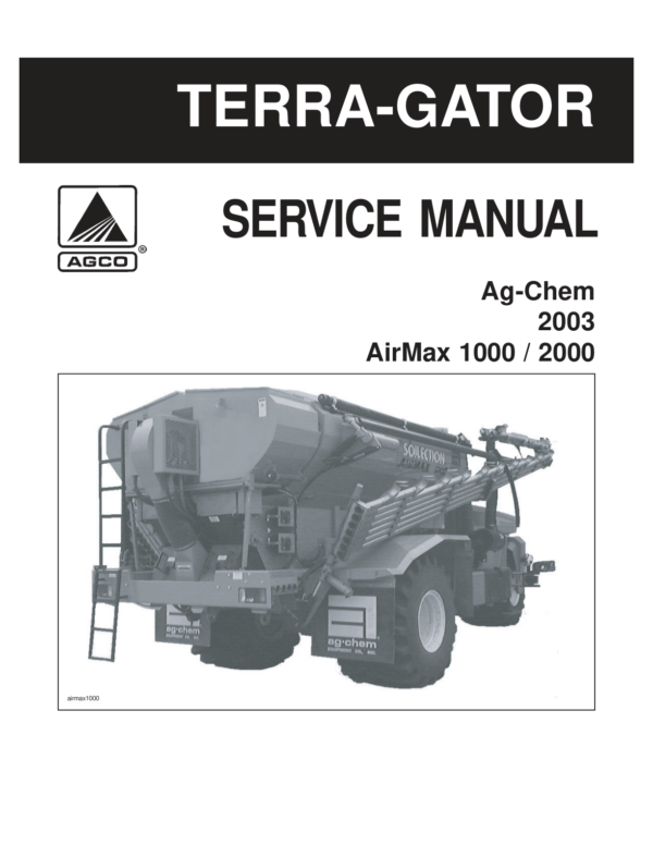
Ag-Chem Air Max 1000, 2000 TerraGator System Service Repair Manual (2003)
$19.00
Manual Included:
- Service Repair Manual: 133 Pages
Specifications:
- Brand: Ag-Chem
- Model: Air Max 1000, 2000
- Type: TerraGator System
- Manuals: Service Repair Manual
- Publication Numbers: AG727577
- Year: 2003
- Language: English
- Format: PDF
- Description
- Reviews (0)
Description
Table of Contents:
- 01-SAFETY GENERIC.pdf
- GENERAL, SAFETY AND TORQUE SPECIFICATIONS
- GENERAL
- Safety Alert Symbol and Signal Words
- FOLLOW SAFETY INSTRUCTIONS
- Towing Other Vehicles / Trailers / Equipment
- Modifications
- Operating the System Safely
- System Boom Safety
- Overhead Electrical Power Lines
- Protect Yourself
- Handle Fuel Safely – Avoid Fires
- Moving Parts
- Maintenance and Service Safety
- Hydraulic Safety
- Work in a Clean Area
- Understand Correct Service
- Remove Paint before Welding or Heating
- Batteries
- Tires and Wheels
- Use Proper Tools
- Lift and Support Machine Properly
- Avoid Eye Contact with Radar
- Exhaust Fumes
- Chemical Safety
- Dispose of Waste Properly
- TORQUE SPECIFICATIONS
- General
- Unified Inch Bolt and Cap screw Values
- Metric Bolt and Cap screw Values
- 4 – Bolt Split Flange
- Split Flange
- Flare and Flareless Port Ends
- Face Seal Port Ends
- Metric Port Ends
- Adapters and Tube Fittings
- 02-Description_Removal_Installation.pdf
- DESCRIPTION, REMOVAL & INSTALLATION
- DESCRIPTION
- Air Max 1000 System
- Air Max 2000 System
- SYSTEM REMOVAL
- SYSTEM INSTALLATION
- 03-Booms_Fan_Rear Manifold.pdf
- BOOMS, FAN & REAR MANIFOLD
- DESCRIPTION
- CENTRIFUGAL FAN
- Description
- Removal
- Installation
- VENTURI MANIFOLD & FUNNELS
- Description
- Venturi Manifold Removal
- Venturi Manifold Installation
- Venturi Block Replacement
- BOOMS
- Description
- Boom Cradle Locks
- Boom Adjustments
- Boom Removal
- Boom Installation
- Boom Suspension Removal
- Boom Suspension Installation
- BAG TEST PROCEDURE
- Description
- Materials and Equipment Required
- Align Boom Tubes to Manifold
- Check Conveyor Gate Opening
- Weight Adjustment Per Boom
- Weight Adjustment Per Tube
- Weight Adjustment Per Nozzle
- Trim Tab Nozzle Adjustment
- 04-Conveyors.pdf
- CONVEYORS & CONVEYOR DRIVES
- DESCRIPTION
- CONVEYOR V-HOODS
- Description
- CONVEYOR APRON CHAINs
- Removal
- Installation
- FRONT CONVEYOR ROLLER AND BEARINGS
- Removal
- Installation
- REAR IDLER ROLLER
- Removal
- Installation
- AIR CLUTCH & OUTER BEARING
- Removal
- Installation
- CONVEYOR DRIVE SPROCKET & DRIVESHAFT
- Removal
- Installation
- HYDRAULIC DRIVE MOTOR & CONVEYOR GEARBOX
- Motor Removal
- Motor Installation
- Gearbox Removal
- Gearbox Installation
- AIR CLUTCH CONTROLS
- Description
- 05-Hydraulic System.pdf
- HYDRAULIC SYSTEM
- DESCRIPTION
- BOOM MOTION & CONVEYOR CIRCUIT
- Description
- Boom Motion Circuit
- Conveyor Circuit
- Hydraulic Block Coil & Cartridge Torque
- Gear Pump Removal
- Gear Pump Installation
- Conveyor Motor Removal
- Conveyor Motor Installation
- FAN CIRCUIT
- Description
- Pump Removal
- Pump Installation
- Fan Motor Removal
- Fan Motor Installation
- HYDRAULIC SYSTEM BLEED PROCEDURE
- Bleed Procedure When Changing Fluid/Filters Only
- Bleed Procedure When Major Components or Hoses Have Been Replaced
- CLEANING THE COMPENSATOR
- TROUBLESHOOTING
- Hydraulic Cylinder Repair
- 06-Electrical.pdf
- ELECTRICAL SYSTEM
- DESCRIPTION
- BOOM MOTION SWITCHES
- Description
- Boom Latch Switch
- Boom Fold Switch
- Boom Hold Down Switch
- Left & Right Boom Leveling Switches
- PRODUCT APPLICATION CONTROL SWITCHES
- Description
- Product Master Switch
- Left & Right Boom Switches
- AIR BOX WIRING
- Boom Sense Pressure Switches
- PWM VALVE WIRING
- PRODUCT RATE SENSOR WIRING
- FULL/EMPTY BIN SENSORS
- FAN SPEED SENSOR
- ELECTRIC ROLL TARP
- Description
- Electrical Control Wiring
- Roll Tarp Mechanical Adjustments & Troubleshooting
- 07-Foam Marker.pdf
- FOAM MARKER SYSTEM
- DESCRIPTION
- FOAM MARKER AIR SYSTEM
- Foam Marker Pressure Regulator
- Troubleshooting
- Gauge
- Foam Marker Enable Solenoid
- Foam Marker Tank, Air Nozzle and Valves
- Removal of the Spray Nozzle from the Bottom of the Tank
- Installation of the Spray Nozzle in the Tank
- FOAM MARKER ELECTRICAL SYSTEM
- Theory of Operation
- Relay K27
- Relay K33 (Left Foam)
- Relay K38 (Right Foam)
- Left/Right Foam Switch
- Double Foam Switch
- Foam Marker System Harness
- Troubleshooting
- 08-Granular.pdf
- GRANULAR CO-APPLICATION SYSTEM
- DESCRIPTION
- GRANULAR BIN
- Description
- Metering Wheels
- Description
- Metering Wheel Drive
- ELECTRICAL CONTROL SYSTEM
- Electric Clutches
- Electric Motor
- Rate Sensor
- Full/Empty Sensors
- 09-Spray Max Liquid.pdf
- SPRAY MAX LIQUID CO-APPLICATION SYSTEM
- DESCRIPTION
- LIQUID TANK
- PRODUCT PLUMBING
- Description
- Product Pump
- Manual Valves, Product Servo Valve, Strainer & Flowmeter
- Electric Boom Shut Off Valves
- Optional Chemical Eductor
- WET BOOM
- SPRAY MAX ELECTRICAL CONTROLS
Be the first to review “Ag-Chem Air Max 1000, 2000 TerraGator System Service Repair Manual (2003)”
You must be logged in to post a review.
Reviews
There are no reviews yet.