

Ag-Chem 6103, 8103, 8104, 8144 CAN Bus Service Repair Manual
$28.00
Manual Included:
- Service Repair Manual: 314 Pages
Specifications:
- Brand: Ag-Chem
- Model: 6103, 8103, 8104, 8144
- Type: CAN Bus
- Manuals: Service Repair Manual
- Publication Numbers: AG133547
- Language: English
- Format: PDF
- Description
- Reviews (0)
Description
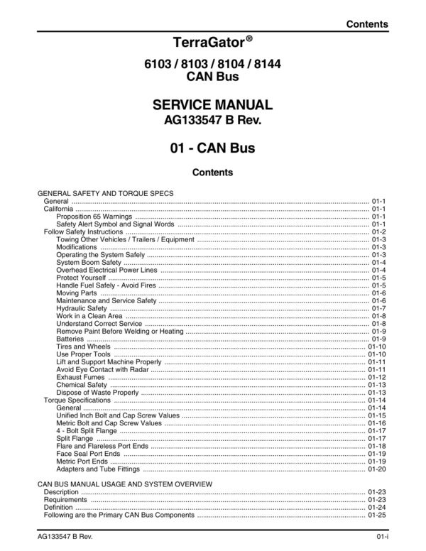
Table of Contents:
- 6103 / 8103 / 8104 / 8144 Can Buss Service Manual
- General Safety and Torque Specs
- General
- California
- Proposition 65 Warnings
- Safety Alert Symbol and Signal Words
- Follow Safety Instructions
- Towing Other Vehicles / Trailers / Equipment
- Modifications
- Operating the System Safely
- System Boom Safety
- Overhead Electrical Power Lines
- Protect Yourself
- Handle Fuel Safely – Avoid Fires
- Moving Parts
- Maintenance and Service Safety
- Hydraulic Safety
- Work in a Clean Area
- Understand Correct Service
- Remove Paint Before Welding or Heating
- Batteries
- Tires and Wheels
- Use Proper Tools
- Lift and Support Machine Properly
- Avoid Eye Contact with Radar
- Exhaust Fumes
- Chemical Safety
- Dispose of Waste Properly
- Torque Specifications
- General
- Unified Inch Bolt and Cap Screw Values
- Metric Bolt and Cap Screw Values
- 4 – Bolt Split Flange
- Split Flange
- Flare and Flareless Port Ends
- Face Seal Port Ends
- Metric Port Ends
- Adapters and Tube Fittings
- CAN Bus Manual Usage and System Overview
- Description
- Requirements
- Definition
- Following are the Primary CAN Bus Components
- Troubleshooting
- 1. Over Temp/Current
- 2. Open Load
- 3. Short To GND
- 4. Short to Bat/OT
- 5. No Error Listed
- Error Codes
- Boom Motion Main Enable and Head Rinse
- Description
- Left-Hand Boom Fold In
- Left-Hand Boom Fold Out
- Right-Hand Boom Fold Out or Boom Unlatch
- Right-Hand Boom Fold In or Boom Latch
- Left-Hand Boom Down
- Left-Hand Boom Up
- Right-Hand Boom Down
- Right-Hand Boom Up
- Boom Motion Enable or Head Rinse
- Power Circuit for the Boom Motion Function
- Ground Circuit for the Boom Motion Functions
- Liquid System Boom Motion Solenoid Ground
- Air-Max Boom Motion Solenoid Ground
- AirSpreader Boom Motion Solenoid Ground
- Power and Ground Circuit for the Boom Motion Enable
- Head Rinse Circuit
- Power for the Head Rinse Circuit
- Ground for the Head Rinse
- Foam Marker Functions
- Description
- Foam Marker Right and Left Solenoid Power Circuit
- Foam Marker Right and Left Solenoid Ground Circuit
- Foam Marker Enable Solenoid Power Circuit
- Foam Marker Enable Solenoid Ground Circuit
- Pump and Sump or Roll Tarp
- Description
- Pump Enable Circuit
- Pump Enable Power Circuit
- Pump Enable Ground Circuit
- Pump Enable Remote Box Power Circuit
- Pump Enable Remote Box Ground Circuit
- Sump Enable Circuit
- Sump Enable Power Circuit
- Sump Enable Ground Circuit
- Sump Enable Remote Box Power Circuit
- Sump Enable Remote Box Ground Circuit
- Tarp Open and Close Circuit
- Tarp Open and Close Power Circuit
- Tarp Magnetic Switch Relay Ground Circuit
- Product Control Circuit
- Description
- Master Apply Power Circuit
- Liquid System
- Air Spreader System
- Vertical Auger Shut Off Dump Valve
- Boom Sense
- Air-Max 1000/2000 System
- Air-Max V System
- New Leader
- Left and Right-Hand Apply Power Circuit
- Ground Circuits
- Liquid System
- Air Spreader System
- New Leader System
- Boom Motion Mast and Tip
- Description
- Boom Mast Right-Hand Tilt Up
- Boom Mast Right-Hand Tilt Down
- Boom Hoist Up
- Boom Hoist Down
- Left-Hand Tip Fold Out
- Left-Hand Tip Fold In
- Right-Hand Tip Fold In and Out
- Power Circuit for the Boom Motion Functions
- Ground Circuit for the Boom Motion Functions
- Boom Section Product Control
- Description
- Liquid System Boom Product Control
- Boom Section Control (Quick Stop) Power Circuits
- Boom Section (Quick Stop) Ground Circuits
- Boom Sense
- Boom Clean Out Circuit
- Boom Clean Out Power Circuit
- Boom Clean Out Ground Circuit
- Wet Boom Pump Circuit
- Wet Boom Pump Power Circuit
- Wet Boom Pump Ground Circuit
- Low-High Beam Light Circuit
- Description
- Low/High Beam Power Circuit
- Low Beam Circuit
- Low Beam Ground Circuit
- High Beam Circuit
- High Beam Ground Circuit
- Work Light Number One Circuit
- Description
- Work Light Number One Power Circuit
- Work Light Number One Ground Circuit
- Work Light Number Two Circuit
- Description
- Work Light Number Two Power Circuit
- Work Light Number Two Ground Circuit
- Chassis Hazard Warning Light Circuit
- Description
- Chassis Warning Light Power Circuit
- Right-Hand Chassis Hazard Circuit
- Left-Hand Chassis Hazard Circuit
- Key Off Power for the Master Module and the I/O Module
- Key Off Power for the I/O Module
- Key Off Power for the Master Module
- Chassis Hazard Ground Circuit
- Chassis Turn Signal Circuit
- Description
- Power for the Chassis Signal Lights
- Right-Hand Signal Light
- Left-Hand Signal Light
- Signal Light Ground Circuit
- Work Light Number Four Circuit
- Description
- Work Light Number Four Power Circuit
- Work Light Number Four Ground Circuit
- Park Lights
- Description
- Park Light Power Circuit
- System Taillight Ground
- Brake Lights Circuit
- Description
- Brake Light Power Circuit
- Brake Light Ground Circuit
- Reverse Light Circuit
- Description
- Reverse Light Power Circuit
- Reverse Light Ground Circuit
- System Hazard Warning Light Circuit
- Description
- System Warning Light Power Circuit
- Right-Hand System Hazard Light Circuit
- Left-Hand System Hazard Light Circuit
- Key Off Power for the Master Module and the I/O Module
- Key Off Power for the I/O Module
- Key Off Power for the Master Module
- System Hazard Light Ground
- System Turn Signal Circuit
- Description
- Power for the System Signal Lights
- Ground for the System Signal Lights
- Nozzle Pressure Gauge Circuit
- Description
- Nozzle Pressure Transducer Power Circuit
- Nozzle Pressure Transducer Ground Circuit
- Nozzle Pressure Signal Circuit
- Nozzle Pressure Gauge Power Circuit
- Nozzle Pressure Gauge Ground Circuit
- Fuel Level Gauge Circuit
- Description
- Fuel Level Signal Circuit
- Fuel Level Ground
- Radar Circuit
- Description
- Radar Power Circuit
- Radar Present Signal
- Radar Signal
- Radar Ground Circuit
- Pump Pressure Gauge Circuit
- Description
- Pump Pressure Gauge Signal Circuit
- Pump Sender Ground Circuit
- Pump Gauge Power
- Pump Pressure Gauge Ground Circuit
- Transmission Converter Open Light
- Description
- Transmission Converter Open Light Power Circuit
- Transmission Converter Open Light Ground Circuit
- Air Pressure Gauge
- Description
- Air Pressure Signal Circuit
- Pump Sump On Circuit
- Description
- Power for the Pump and Switch Lights
- Ground for the Pump Switch Light
- Ground for the Sump Switch Light
- Foam Marker On
- Description
- Power for the Foam Marker Switch Light
- Ground for the Foam Marker Switch Light
- Beacon Circuit
- Description
- Beacon Power Circuit
- Beacon Ground Circuit
- I/O Modules and Power Dividers
- Description
- I/O Module Power and Ground Circuits
- Front Chassis I/O Interface Module Power Supply
- Front Chassis I/O Module Ground
- System I/O Module Power Supply
- System I/O Ground Circuit
- Power Divider Power and Ground Circuits
- Chassis Power Divider Power and Ground
- System Power Divider Power and Ground
- HVAC-Cab Pressurization Blower Circuit
- Description
- Pressure Blower Power Circuit
- HVAC Blower Motor Ground Circuit
- HVAC Power Circuit
- Overhead HVAC Power
- Under the Seat HVAC Power
- Fan Switch Three Speed Circuit
- A/C Switch Circuit
- Heater Switch Circuit
- HVAC Ground Circuit
- Radio Circuit
- Description
- Radio Switched Power Circuit
- Radio Unswitched Memory Power
- Radio Ground Circuit
- Speaker Wires
- Front Speaker Wires
- Rear Speaker Wires
- Seat Circuit
- Description
- Seat Power Circuit
- Seat Ground Circuit
- Windshield Washer Circuit
- Description
- Windshield Washer Power Circuit
- Windshield Washer Ground Circuit
- Windshield Wiper Circuit
- Description
- Wiper in the Off/Park Position
- Wiper in the Low Speed Position
- Wiper in the High Speed Position
- Wiper Ground Circuit
- Work Light Number Three Circuit
- Description
- Work Light Number Three Power Circuit
- Right-Hand Circuit
- Left-Hand Circuit
- Work Light #3 Ground Circuit
Be the first to review “Ag-Chem 6103, 8103, 8104, 8144 CAN Bus Service Repair Manual”
You must be logged in to post a review.
Reviews
There are no reviews yet.