

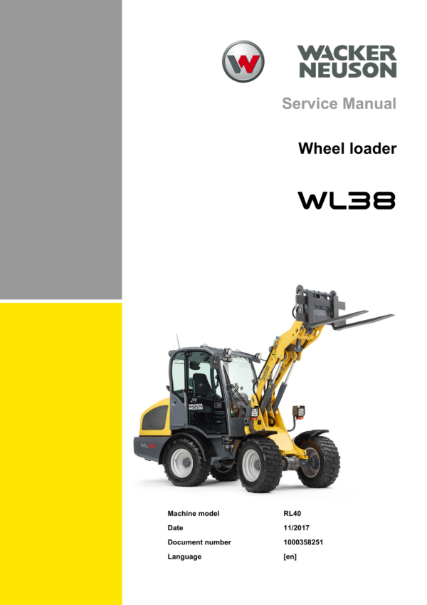
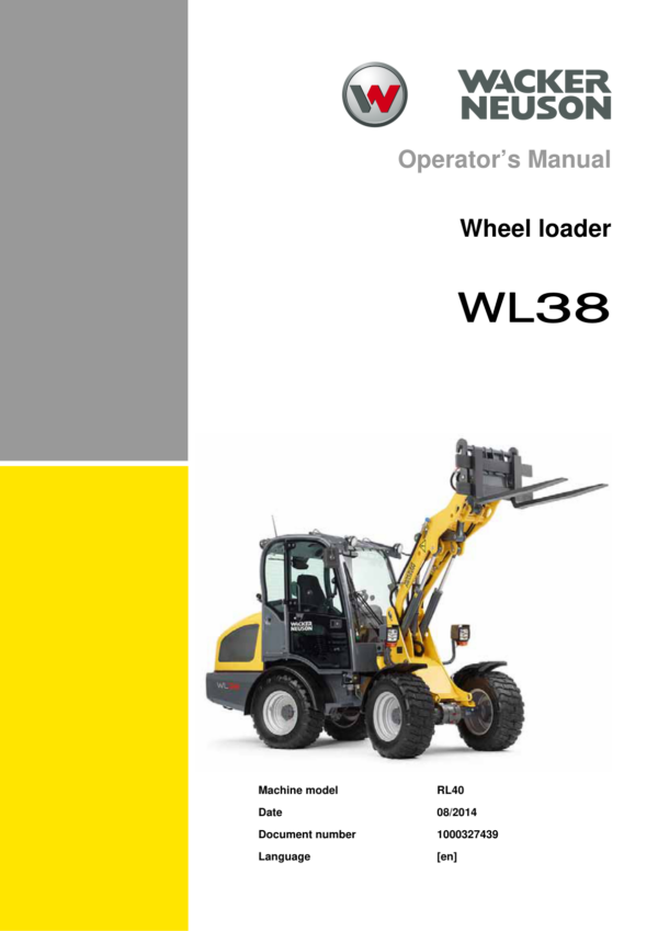
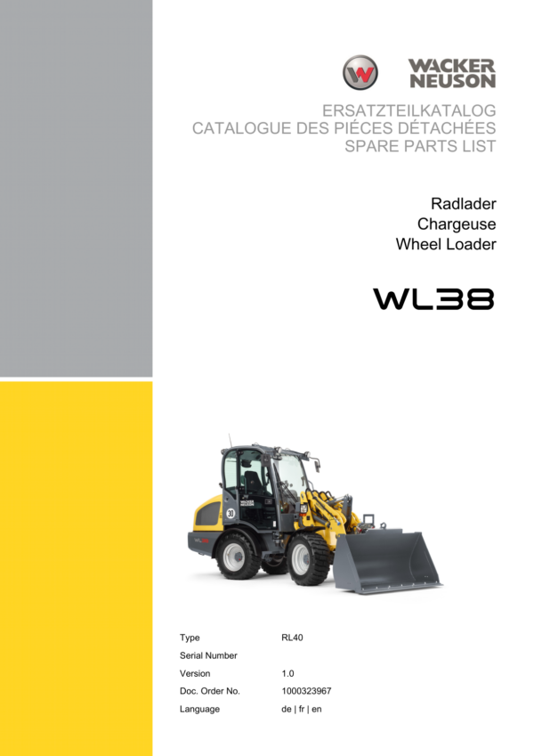
Wacker Neuson WL38 Wheel Loader Service Repair Manual
$44.00
Manual Included:
- Service Repair Manual: 372 Pages
- Operators Manual: 254 Pages
- Spare Parts Catalog: 1041 Pages
Specifications:
- Brand: Wacker Neuson
- Model: WL38
- Type: Wheel Loader
- Manuals: Service Repair Manual
- Language: English
- Category: Wacker Neuson
- Format: PDF
- Description
- Reviews (0)
Description
Table of Content – Wacker Neuson WL38 Manual
- Introduction
- Notice on This Service Manual
- Technical Data
- Tightening Torques
- Safety Instructions
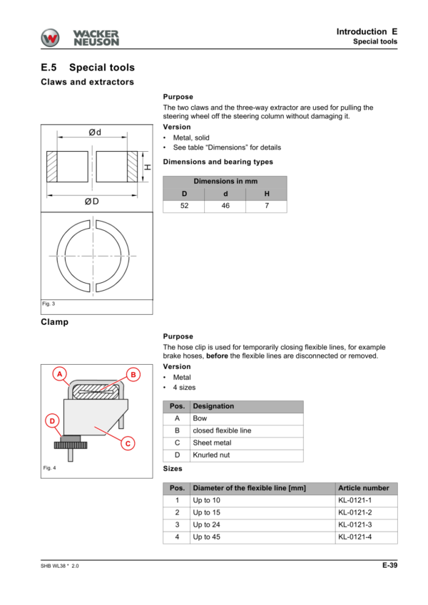
- Special Tools
- Operation
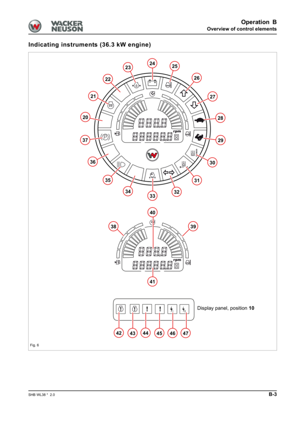
- Overview of Control Elements
- Indicator Lights and Warning Lights (Overview)
- Maintenance
- Information on Maintenance
- Maintenance Overview
- Lubrication Plan
- Fluids and Lubricants
- Maintenance Accesses
- Cleaning and Maintenance
- Lubrication Work
- Fuel System
- Engine Lubrication System
- Cooling System
- Air Filter
- V-Belt/Toothed Belt
- Hydraulic System
- Electrical System
- Heating, Ventilation and Air Conditioning System (Option)
- Washer System
- Axles/Traveling Drive
- Braking System
- Tires
- Maintenance and Servicing Work on Attachments
- Maintenance of Options
- Exhaust Gas Treatment of Perkins 404F Engine
- Exhaust Gas Treatment of Deutz TCD 2.9 L4 Engine (55.4 kW)
- Engine
- Complete Component (36.3 kW Engine)
- Complete Component (44.7 kW Engine)
- Alternator (44.7 kW)
- Starter M001 (44.7 kW)
- Diesel Particulate Filter (44.7 kW)
- Complete Component (Deutz Engine 55.4 kW)
- V-Belt (55.4 kW)
- Alternator (55.4 kW)
- Removing/Installing the Starter Motor (55.4 kW)
- Removing/Installing the Fuel Tank
- Cooling
- Removing/Installing the Coolant Reservoir
- Removing/Installing the Radiator
- Removing/Installing Fan Blades
- Traveling Drive
- Traveling Drive Hose Routing
- M-Drive Hose Routing
- Variable Displacement Pump
- Variable Displacement Motor M5
- Hydraulic Oil Tank Z55
- Removing/Installing the Cardan Shaft
- M-Drive (Option)
- Troubleshooting
- Axles
- Front Axle
- Rear Axle
- Type Label – Front/Rear Axle
- Braking System
- Overview
- Service/Parking Brake
- Removing/Installing the Parking Brake
- Removing/Installing the Parking Brake Bowden Cable
- Master Brake Cylinder
- Steering System
- Hose Routing
- Removing/Installing the Steering Wheel
- Removing/Installing the Steering Column
- Removing/Installing Steering Cylinder A01
- Steering Orbitrol S1
- Work Hydraulics
- Overview
- Hose Installation
- Gear Pump P45
- Removing/Installing Lock Cylinder A4
- Removing/Installing the Lock Pin
- Removing/Installing the Tilt Cylinder
- Removing/Installing the Loader Unit
- Removing/Installing the Lift Cylinder
- Removing/Installing the Reversing Lever
- Removing/Installing Solenoid Valve V30
- Removing/Installing Pressure Relief Valve V60
- Removing/Installing the Quickhitch
- Removing/Installing the Control Valve
- Designation of Hydraulic Components
- Hydraulics Diagram – HDS21/4 with HDS21/1 or 6/2 Multiple-Way Valve
- Hydraulics Diagram – HDS21/4 with HDS21/2
- Hydraulics Diagram – HDS21/3 with HDS21/1 or 6/2 Multiple-Way Valve
- Hydraulics Diagram – HDS21/3 with HDS21/2
- Hydraulics Diagram – HDS21/4 High Flow
- Electrical System
- Removing/Installing the Machine Control Unit
- Joystick
- Malfunctions of the Machine Electronics
- Electrical Diagram – Power Supply
- Electrical Diagram – Power Supply for Control Electronics and Joystick Lighting
- Electrical Diagram – Deutz Engine
- Electrical Diagram – Perkins Engine 404F-22
- Electrical Diagram – Perkins Engine 404D-22
- Electrical Diagram – Bauser LED Instrument
- Electrical Diagram – Ciam Instrument
- Electrical Diagram – Travel Function
- Electrical Diagram – Lights According to StVZO
- Electrical Diagram – Turn Indicator System and Horn
- Electrical Diagram – Wiper/Washer System
- Electrical Diagram – Working Lights and Rotating Beacon
- Electrical Diagram – Front/Rear Electrical Connection, Hydro Comfort, Addition A and Continuous Operation of the 3rd Control Circuit
- Electrical Diagram – Hydraulic System
- Electrical Diagram – Air Conditioning and Seat
- Electrical Diagram – Radio, Cigarette Lighter, Interior Light and Safe Load Indicator
- Designation of Electrical Components
- Trim
- Removing/Installing the Engine Cover
- Removing/Installing the Bottom Plate
- Removing/Installing the Trailer Power Outlet
- Removing/Installing the Trailer Coupling/Chassis Cover
- Removing/Installing the Counterweight
- Cabin
- Removing/Installing the Operator Seat
- Removing/Installing the Indicating Instrument
- Removing/Installing the Starter
- Removing/Installing the Tilt Cylinder
- Removing/Installing the Wiper Motor
- Heating
- Removing/Installing the Cabin
- Malfunctions
- Towing a Machine
- Error Code Lists
Be the first to review “Wacker Neuson WL38 Wheel Loader Service Repair Manual”
You must be logged in to post a review.


Reviews
There are no reviews yet.