







Wacker Neuson TH625 Telehandler Service Repair Manual
$40.00
Manual Included:
- Service Repair Manual: 420 Pages
- Operators Manual: 354 Pages
- Spare Parts Catalog: 144 Pages
Specifications:
- Brand: Wacker Neuson
- Model: TH625
- Type: Telehandler
- Manuals: Service Repair Manual
- Language: English
- Category: Wacker Neuson
- Format: PDF
- Description
- Reviews (0)
Description
Table of Content – Wacker Neuson TH625 Manual
- Cab Overview, Use and Operation
- Machine Outside View
- Inside of Cab (Overview)
- Instrument Panel, Multifunctional Lever and Switch Consoles (Overview)
- Fields of Application and Using a Machine with an Attachment
- Legal Regulations Regarding Machine Operation
- Type Labels and Component Numbers
- Key-Based Drive Interlock (Option)
- Drive Interlock with Code Input (Option)
- Battery Master Switch (Option)
- Avoiding Running the Engine Under Low-Load Conditions
- Stopping the Diesel Engine
- Jump-Starting the Diesel Engine (External Battery)
- Pressure Relief on the Quickhitch Couplers
- Overview of Steering Modes (Option)
- Steering Synchronisation (Wheels Front/Rear Axles)
- Low-Speed Control (Option)
- Rear Hydraulic Additional Control Circuit (Option)
- Hydraulic Connection for Tipping Trailer (Option)
- Autohitch Trailer Coupling (Option)
- Automatic Trailer Coupling (Option)
- Hydraulic Trailer Brake Connection (Option)
- Fitting Attachments from Other Manufacturers (Option)
- Towing the Machine
- Specifications
- Model and Trade Names (Overview)
- Frame
- Diesel Engine
- Drive
- Axles
- Service and Parking Brake (Disc Brake)
- Steering System
- Work Hydraulics
- Electrical System
- Tyres
- Machine Weight and Axle Loads
- Trailer Couplings: Trailer Weight/Drawbar Load
- Sound Levels and Noise
- Vibrations, Oscillation and Acceleration Values
- Coolant Compound Table
- Tightening Torques
- Standard Bucket Payloads
- Pallet Forks Payloads
- Dimensions with Standard Bucket
- Dimensions with Pallet Forks
- Maintenance and Service Work
- Explanation of Symbols on the Maintenance Label
- Maintenance Label
- Fluids and Lubricants
- Maintenance Plan (Overview)
- Important Notice Regarding Maintenance Work
- Safety Strut for Telescopic Boom
- Fuel System
- Refuelling
- Checking/Cleaning the Additional Fuel Filter (Water Separator, Option)
- Bleeding the Fuel System
- Replacing the Fuel Filter
- Diesel Engine Lubrication System
- Filling Up Engine Oil
- Changing the Engine Oil
- Replacing the Engine Oil Filter Cartridge
- Diesel Engine and Hydraulics Cooling System
- Temperature Gauge: Diesel Engine Coolant
- Filling Up Coolant
- Cleaning the Radiator Fins
- Draining Coolant
- Air Filter
- Replacing the Filter Cartridge
- V-Belts
- Hydraulic System
- Monitoring the Hydraulic Oil and Return Filter Indicator Lights
- Checking the Hydraulic Oil Level Once a Day
- Filling Up Hydraulic Oil
- Changing the Filter Insert
- Replacing Hydraulic Oil
- Important Notices on the Use of Biodegradable Oil
- Checking Hydraulic Pressure Lines
- Oil Levels: Rear Axle Transfer Gearbox
- Oil Levels: Front and Rear Axle Differentials
- Oil Levels: Front and Rear Axle Planetary Drives
- Lubrication Work
- Lubrication Points on the Telescopic Boom (Overview)
- Lubricating with the Central Lubrication System (Option)
- Setting the Lubrication and Break Times
- Central Lubrication System Diagram
- Installing the High-Pressure Hoses on the Central Lubrication System
- Instructions for Troubleshooting in Case of Central Lubrication System Blocking
- Repairing a Blocking Distributor of the Central Lubrication System
- Troubleshooting Table for Central Lubrication System
- Maintenance of the Brake System
- Tyres
- Changing Wheels
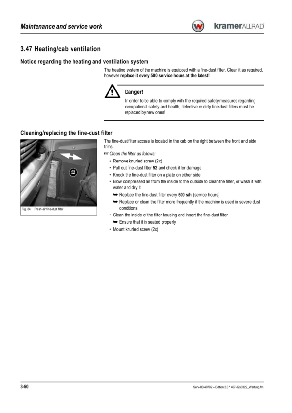
- Heating/Cab Ventilation
- Air Conditioning (Option): Maintenance
- Functional and Visual Checks of the Air Conditioning
- Cleaning the Heat Exchanger (Condenser)
- Maintenance of the Electrical System
- Maintenance of the Automatic Trailer Coupling (Option)
- General Maintenance and Cleaning Work
- Maintenance of Attachments and Work Equipment
- Engine
- Diesel Engine Diagrams
- Diagnosis/Fuel Preheater (Electrical Diagrams)
- Manual Throttle Diagrams
- Engine Designation
- Fuel Specification
- Coolant Specification
- Diesel Engine TD 2009 L04 (Overview)
- Electric Components on Engine (Overview)
- Lube Oil Circuit
- Cooling
- Adjusting the Cable Pull for Speed Regulation
- Fuel System
- Replacing the Cylinder Head Gasket
- Removing/Installing the Fuel Injection Pump
- Mounting the Fuel Injection Pump
- Removing/Installing the Fuel Injectors
- Sealing the Coolant Pump
- Removing/Installing the Thermostat
- Checking the Thermostat
- Assembly Instructions: Replacing the Visco Clutch
- Tightening Torque Table
- Diesel Engine Malfunctions
- Drive
- Drive (Hydraulic Diagram)
- Drive Diagrams
- Making Settings with the Laptop
- Error: Incorrect Tool Key
- Importing New Data
- Drive Electronics PLUS+1 Mode Description
- Reading Out/Deleting the Error History
- Deleting the Error History
- Switching the Inching Potentiometer On/Off
- Reading in the Inching Potentiometer Again
- Reading in the Inching Potentiometer
- Switching the Creep Gear Potentiometer On/Off
- Switching On the Creep Gear Potentiometer
- Reading in the Creep Gear Potentiometer
- Modifying the Load Stabiliser Settings
- Error Code Table
- Towing and Transporting the Machine
- Hydraulic Pump H1 (Model 407 02) Test Ports and HP Valves (Overview)
- Hydraulic Pump H1 (Model 407 02) Proportional Valve and Electronics (Overview)
- Variable Displacement Motor H1 110 cm³/rev (Overview)
- Variable Displacement Motor H1B (Overview)
- Model 407 02 Test Report
- Error Description for Test Report Model 407 02
- Drive with Hydraulic Pump H1 (Hydraulic Circuit)
- Checking the Idling Speed
- Checking/Adjusting Starting Speed
- Adjusting Boost Pressure
- Checking High Pressure
- Checking Driving Direction Identification
- Checking the Energisation of the Driving Direction Identification
- Checking Engine Droop (Variable Displacement Pump)
- Setting the Pump Droop Speed
- Setting Engine Droop/Control Initiation of the Hydraulic Motor
- Setting Maximum Speed
- Troubleshooting Boost-Pressure Errors (Diagram)
- Checking High Pressure (HP Valves)
- Checking Pump Engine Droop, Driving Direction Identification and Differential Pressure Measurement
- Axles
- Differential Lock Diagrams
- Axle Type Label
- Front Axle Screw Connections
- Rear Axle Screw Connections
- Drain, Fill and Check Plug – Front Axle
- Drain, Fill and Check Plug – Rear Axle
- Front Axle Tightening Torques (Nm)
- Rear Axle Tightening Torques (Nm)
- Sealing Work
- Brakes
- Brake Diagrams
- Brakes (Hydraulic Diagram)
- Brake Circuit
- Trailer Brake Valve Circuit
- Service Brake Function
- Parking Brake Circuit
- Service Brake
- Sealing the Brake Calliper
- Bleeding the Brake System with Bleed Equipment
- Setting the Brake Pedal with the Inching Potentiometer
- Steering System
- Steering System (Hydraulic Diagram)
- Steering Circuit with Final-Position Synchronisation
- Steering Circuit with Front, Four-Wheel and Crab Steering
- Steering System Adjustment
- Hydraulic Ports on Servostat
- Pressure Relief Valve: Adjustment
- Sealing Steering Rams
- Checking the Steering Mode Valve
- Checking a Steering Ram
- Overview of Steering Ram Setting
- How to Check and Set the Steering Rams
- Checking the Track Setting (1)
- Correcting the Track Setting (2)
- Steering Misalignment During Final-Position Synchronisation (3)
- Adjustment Work
- Checking Steering Synchronisation (4)
- Work Hydraulics
- 20 kph 4-Fold Control Valve (Hydraulic Diagram)
- 30 kph 5-Fold Control Valve (Hydraulic Diagram)
- Hydraulics Legend
- Raising/Lowering (Diagrams)
- Raising/Lowering the Telescopic Boom (Hydraulic Diagram)
- Raising/Lowering the Telescopic Boom, Load Stabiliser (Hydraulic Diagram)
- Dumping In/Out, Tilt Ram Lock (Electrical Diagrams)
- Dumping Out (Hydraulic Diagram)
- Tilt Ram Lock (Hydraulic Diagram)
- Extending/Retracting the Telescopic Boom (Black/White) (Electrical Diagrams)
- Extending/Retracting the Telescopic Boom/Proportional (Electrical Diagrams)
- Retracting/Extending the Telescopic Boom (Hydraulic Diagram)
- Locking/Unlocking the Quickhitch (Black/White) (Electrical Diagrams)
- Quickhitch Diagram Designations (Black/White, Lock/Unlock)
- Locking/Unlocking the Quickhitch Proportionally (Electrical Diagrams)
- Quickhitch Diagram Designations (Proportional, Lock/Unlock)
- Locking (Hydraulic Diagram)
- Locking/Additional Control Circuit (Hydraulic Diagram)
- Locking/Return Without Pressure (Hydraulic Diagram)
- Safe Load Indicator (Electrical Diagrams)
- Overload Cutoff (Hydraulic Diagram)
- Load Stabiliser (Electrical Diagrams)
- Additional Control Circuit/Tipping Trailer (Hydraulic Diagram)
- Tipping Trailer (Hydraulic Diagram)
- Autohitch (Hydraulic Diagram)
- Autohitch/Tipping Trailer (Hydraulic Diagram)
- Additional Function (Electrical Diagrams)
- Autohitch/Additional Control Circuit/Tipping Trailer (Hydraulic Diagram)
- Test Report for Hydraulics 407-02 (2506)
- Work Hydraulics Oil Supply
- Pump Pressure/Work Hydraulics Test Port
- Control Valve (Overview)
- Control Valve Design
- Checking and Setting the Work Hydraulics
- 7-Fold Pilot Valve (Overview)
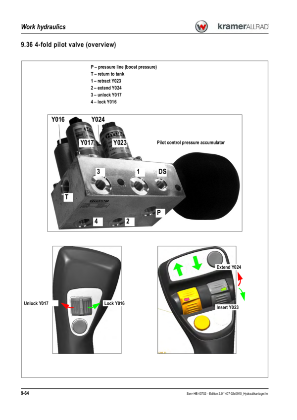
- 4-Fold Pilot Valve (Overview)
- Pilot Control Circuit
- Load Stabiliser Circuit
- Lift Ram Circuit
- Tilt Ram Circuit
- 3rd Control Circuit
- Additional Control Circuit and Rear Tipping Trailer
- Tilt Ram Lock Circuit
- Autohitch and Tipping Trailer Ports
- Overload Cutoff Circuit
- Load Stabiliser
- Valve for Tilt Ram Lock
- Tipping Trailer and Additional Control Circuit Valve
- Work Hydraulics/Steering System Priority Valve
- Valves (General Overview)
- Lift Ram (Sealing Work)
- Tilt Ram (Sealing Work)
- Push-Out Ram
- Compensating Ram
- Control Ram (Quickhitch Frame) (Sealing Work)
- Lift, Tilt and Push-Out Rams: Velocity
- Usable Consumer Pressure at Additional Control Circuit (Option)
- Overload Control (Smart Handling)
- Overview of Safe Load Indicator
- Setting the Safe Load Indicator (0% Point)
- Setting the Safe Load Indicator (100% Point Stability)
- Inspection Plan for Overload Control (Model 407 Telehandler)
- Testing Without Any Load
- Testing with Load
- Functional Description of Overload Control (Smart Handling)
- Electric Components
- Circuit Diagram: Overload Control Enabled
- Circuit Diagram: Automatic Retraction Off
- Overview of Valves
- Overview of Valve Connections and Ports
- Circuit Diagram: Overload Control
- Circuit Diagram Legend
- Extend (Solenoid Valve Y102) (Circuit Diagram)
- Pallet Forks Mode (Circuit Diagram)
- Tip Switch S084 Pressed (Circuit Diagram)
- Overload Control Relay
- Installation Position: Overload Control Relay
- Electrical System
- Lights (Diagrams)
- Working Lights (Diagrams)
- Turn Indicators/Horn/Rotating Beacon (Diagrams)
- Window Heating/Front Socket (Electrical Diagrams)
- Wipe/Wash System (Electrical Diagrams)
- Seat/Air Conditioning System (Diagrams)
- Multimedia/Monitoring/Cigarette Lighter (Electrical Diagrams)
- Cab Wiring Harness 1000256306-01
- Cab Wiring Harness Legend
- Engine Wiring Harness 1000245802
- Engine Wiring Harness Legend
- Frame Wiring Harness 1000256307
- Frame Wiring Harness Legend
- Cab Wiring Harness (Overload Control)
- Cab Wiring Harness Legend
- Frame Wiring Harness (Overload Control)
- Frame Wiring Harness (Overload Control) Legend
- Ohm’s Law: Current, Voltage, Resistance and Power
- Measuring Equipment and Measuring Methods
- Terminal Description
- Colour Coding of Electric Lines
- Switching Relay Function
- Fuse Assignment
- Switching Relay Assignment on Board
- Switching Relay Assignment on Bracket
- Main Fuse Box with Relays in the Engine Compartment
- Electric Units
- Connector Description (Overview)
- Switch Assignment on Board (Overview)
- Switch Assignment on Instrument Panel (Overview)
- Control Lever (Black/White Control)
- Joystick (Black/White Function)
- Joystick: Retracting/Extending the Telescopic Boom (Black/White)
- Joystick: Unlocking/Locking the Telescopic Boom (Black/White)
- Control Lever (Proportional Control)
- Joystick (Proportional Function)
- Joystick: Retracting/Extending the Telescopic Boom (Proportional)
- Joystick: Unlocking/Locking the Telescopic Boom (Proportional)
- Additional Control Circuit with Potentiometer (Proportional)
- Proportional Controls Connector Assignment (Overview)
- Proportional Controls (Overview and Connections)
- Retrofitting a Rotating Beacon
- Retrofitting the Backup Warning System
- Retrofitting Two Front Working Lights
- Retrofitting Two Rear Working Lights
- Retrofitting a Rear 7-Pole Socket
- Retrofitting a Front 4-Pole Socket
- Retrofitting Two Working Lights on the Telescopic Boom (From Mid-2011)
Be the first to review “Wacker Neuson TH625 Telehandler Service Repair Manual”
You must be logged in to post a review.
Reviews
There are no reviews yet.