

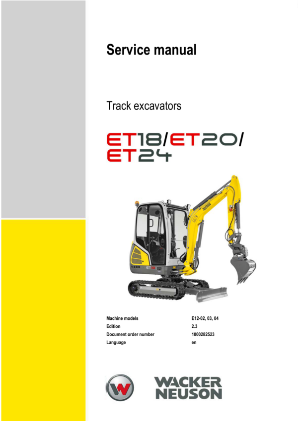
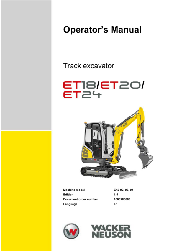




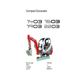
Wacker Neuson ET18, ET20, ET24 Excavator Service Repair Manual
$47.00
Manual Included:
- Service Repair Manual: 290 Pages
- Operators Manual: 286 Pages
- Spare Parts Catalog: 532 Pages
Specifications:
- Brand: Wacker Neuson
- Model: ET18, ET20, ET24
- Type: Track Excavator
- Manuals: Service Manual, Operators Manual, Spare Parts Catalog
- Language: English
- Format: PDF
- Description
- Reviews (0)
Description
Table of Content – Wacker Neuson ET18, ET20, ET24 Manual
-
Operation
- Information on this service manual
- Identification of warnings and dangers
- Explanation of symbols and abbreviations
- Designated use and exemption from liability
- Labels
- Machine overview
- Cabin
- Display element and switches
- Cabin and control stand
- Control lever base
- Accelerator actuation
- High speed
- Automatic engine speed setting
- Brakes
- Protective structures
- Emergency exit
- Swiveling console limit
- Emergency lowering
- Releasing hydraulic pressure
- Hydraulic connections
- Parking the machine
- Engine compartment overview
- Valve compartment overview
- Operating hydraulics
- Fire extinguisher
- Towing the machine
-
Technical data
- Models and trade names
- Engine
- Engine capacities
- Traveling drive and axles
- Tires and tracks
- Fuel injection pump
- Coolant
- Brakes
- Operating hydraulics
- Speed
- Hose identification code
- Electrical system
- Tightening torques
- Powertilt
- Noise emissions
- Vibration
- Ground clearance and ground pressure
- Weight
- Excavator forces
- Cylinder speeds
- Payload and lift capacity
- Dimensions
- Kinematics
- Measuring live ring tolerance
-
Maintenance
- Information on maintenance
- Service package
- Fluids and lubricants
- Maintenance label
- Maintenance plan
- Overview of maintenance areas
- Maintenance accesses
- Removing and installing the cabin or canopy
- Raising the seat console
- Fuel system
- Engine lubrication system
- Cooling system
- Air filter
- Heating, ventilation and air conditioning
- Washer system
- V-belt
- Pressure check
- Test report
- Hydraulic system
- Traveling drive
- Tires and tracks
- Maintenance of attachments
- Lubrication work
- Maintenance of options
- Electrical system
- Cleaning and maintenance
- Resetting the maintenance meter
-
Engine
- Engine 3TNV76-SNSE12
- Valve clearance
- Cylinder-head bolts
- Injection nozzles
- Injection time
- Injection pump
- Engine speed
- Compression
- Coolant thermostat
- Temperature switch
- Oil pressure switch
- Coolant circuit
- Coolant and fuel hoses
- Crankcase vent
- Glow plugs
- Engine 3TNV80F-SSNS1
- Fuel system
- Cooling system
- Altitude-dependent output reduction
- Engine malfunctions
-
Hydraulic system
- Overview
- Hydraulic pump
- Variable displacement and twin gear pump
- Summation control
- Pilot oil supply unit
- Hydraulic pump disassembly and assembly
- Main valve block
- Pilot valves
- Drive valve
- Auxiliary hydraulics changeover valve
- Collector unit
- Breather filter
- Pilot control filter
- Bladder-type accumulator
- Traveling drive
- Swivel unit
- Swivel joint
- Regeneration
- Boom load-retaining valve
- Bucket pre-tension
- Cylinder speed test specifications
-
Electrical system
- Ohm’s Law and electrical power
- Measuring equipment and methods
- Relays
- Electric units
- Fuses and relays
- Alternator
- Starter
- Socket
- 12 V power outlet
- Radio
- Engine and chassis wiring harnesses
- Canopy wiring harness
- Cabin wiring harness
- Seat console wiring harness
- Working light wiring harness
- Roof light wiring harnesses
- Proportional controls wiring harness
- Quickhitch wiring harness
- Safe load indicator wiring harness
- Strand lists
-
Diagrams
- Hydraulics diagram legend
- Hydraulics diagram ET18
- Third control circuit hydraulics diagram ET18
- Hydraulics diagram ET20
- Third control circuit hydraulics diagram ET20
- Hydraulics diagram ET24
- Third control circuit hydraulics diagram ET24
- Options hydraulics diagrams
- Wiring diagram legend
- Wiring diagrams
-
Options
- Automatic engine speed setting
- Grab control circuit
- Hydraulic Easy Lock quickhitch
- Third control circuit
- Proportional controls
- Hammer operation
- ISO and SAE controls
- Travel signal
- Vertical Digging System
- Safe load indicator
- Hose burst valve
- Immobilizer
- Telematic
-
PowerTilt PTS4.5
- General instructions
- General safety instructions
- Checking the product
- Decompression valve
- Testing the hydraulic system
- Specifications and requirements
- Tools
- Removing the bucket or equipment
- Removing the PowerTilt from the machine
- Individual components
- Replacement sealing and bearing kits
- Dismantling the base blocks
- Removing the end cap
- Removing the shaft
- Removing the piston tube
- Removing and fitting seals and bearings
- Fitting the piston tube
- Fitting the shaft
- Installing the end cap
- Fitting the base blocks
- Lubrication and tests
- Replacing the decompression valve
- Securing the PowerTilt on the machine
- Fitting a bucket or equipment
- Adjusting PowerTilt play
- Troubleshooting
Be the first to review “Wacker Neuson ET18, ET20, ET24 Excavator Service Repair Manual”
You must be logged in to post a review.


Reviews
There are no reviews yet.