

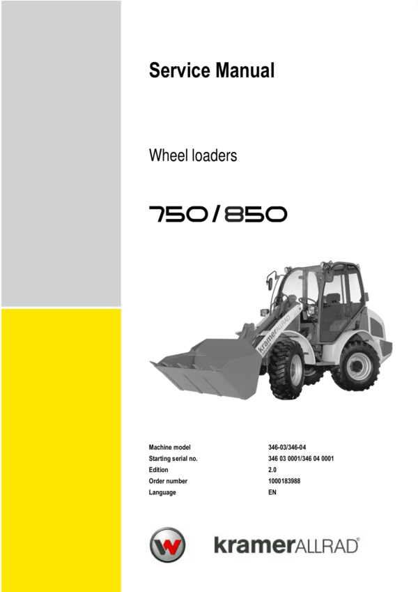
Wacker Neuson 750, 850 Wheel Loader Service Repair Manual
$27.00
Manual Included:
- Service Repair Manual: 256 Pages
Specifications:
- Brand: Wacker Neuson
- Model: 750, 850
- Type: Wheel Loader
- Manuals: Service Repair Manual
- Language: English
- Category: Wacker Neuson
- Format: PDF
- Description
- Reviews (0)
Description
Table of Content – Wacker Neuson 750, 850 Manual
- Cab Overview, Labels and Options
- Inside of Cab: Overview
- Instrument Panel, Multifunctional Lever and Drive Lever: Overview
- Overview of Exterior of Machine
- Important Information on This Manual
- Wheel Loader Warranty
- Models and Trade Names: Overview
- Brief Description of the Wheel Loader
- Fields of Application and Using the Wheel Loader with an Attachment
- Regulations
- Type Labels and Component Numbers
- Signs and Symbols
- Telltales and Warning Lights: Description
- Drive Interlock with Code Input (Option)
- Key-Based Drive Interlock (Option)
- Battery Master Switch (Option)
- Oil and Fuel Preheater (Option)
- Jump-Starting the Engine (External Battery)
- Manual Throttle (Option)
- Low-Speed Control (Option)
- Electric Connection – Front Socket (Option)
- Working Lights
- Rotating Beacon (Option)
- Backup Warning System (Option)
- Additional Control Circuit for Attachments (Option)
- Hose Burst Valve Safety Feature (Option)
- Towing the Machine
- Specifications
- Models and Trade Names: Overview
- Frame
- Engine
- Power Train
- Variable Displacement Pump
- Boost Pump
- Variable Displacement Motor
- Axles
- Brakes
- Steering System
- Work Hydraulics
- Electrical System
- Tyres
- Weights
- Noise Levels
- Vibration
- Coolant Compound Table
- Tightening Torques and Conversion Tables
- Payloads
- Wheel Loader Dimensions with Bucket (Model 346-03)
- Wheel Loader Dimensions with Bucket (Model 346-04)
- Wheel Loader Dimensions with Pallet Forks (Models 346-03/346-04)
- Maintenance and Service Work
- Explanation of Symbols on the Maintenance Label
- Maintenance Label
- Fluids and Lubricants
- Maintenance Plan
- Important Information on Maintenance and Service Work
- Fuel System
- Replacing the Fuel Filter
- Cleaning the Fuel Pump Screen Filter
- Bleeding the Fuel System
- Checking and Filling Up the Engine Oil
- Changing Engine Oil
- Replacing the Engine Oil Filter Cartridge
- Cleaning the Radiator Fins of the Oil/Water Radiator
- Checking the Coolant Level
- Draining Coolant
- Filling Up Coolant
- Hydraulic System
- Checking Hydraulic Pressure Lines
- Monitoring the Hydraulic Oil Reflux Filter
- Maintenance of the Hydraulic Oil Reflux Filter
- Checking the Hydraulic Oil Level
- Filling Up Hydraulic Oil
- Replacing Hydraulic Oil
- Oil Levels: Rear Axle Transfer Gearbox
- Oil Levels: Front and Rear Axle Differentials
- Oil Levels: Front and Rear Axle Planetary Drives
- Air Filter Maintenance
- Maintenance of the Diesel Engine V-Belt
- Lubrication Work
- Lubricating the Loader Unit
- Maintenance of Attachments
- Lubricating with the Central Lubrication System (Option)
- Mounting the High-Pressure Hoses
- Instructions for Troubleshooting Central Lubrication System Blockages
- Repairing a Blocked Distributor
- Troubleshooting Table
- Brake System Maintenance
- Tyre Maintenance
- Changing Wheels
- Maintenance of Cab Heating and Fresh Air Filter
- Air Conditioning Maintenance (Option)
- Maintenance of the Electrical System
- Battery Maintenance
- General Maintenance Work
- Cleaning Inside the Cab
- Cleaning the Seat Belt
- Cleaning the Exterior of the Machine
- Cleaning the Engine Compartment
- Screw Connections and Hinges
- Maintenance Work for Aggressive Media (Option)
- Engine
- Engine Designation
- Fuel Specification
- Coolant Specification
- Electrical Components Overview
- Diesel Engine D 2011 L04 W Overview
- Engine Oil Cooling
- Belt Drive with Cooling Ports
- Fuel System
- Checking and Adjusting Valve Clearance
- Replacing the Fuel Injection Pump
- Switching Off Minus Compensation
- Heating Connection
- Removing and Mounting the Cylinder Head
- Sealing the Bleed Valve
- Sealing the Intake and Exhaust Manifold
- Replacing the Toothed Belt and Tensioning Pulley
- Engine Trouble
- Power Train
- Variable Displacement Pump Test Ports (20 kph)
- Variable Displacement Pump (20 kph)
- Variable Displacement Pump Test Ports (30 kph)
- Variable Displacement Pump (30 kph)
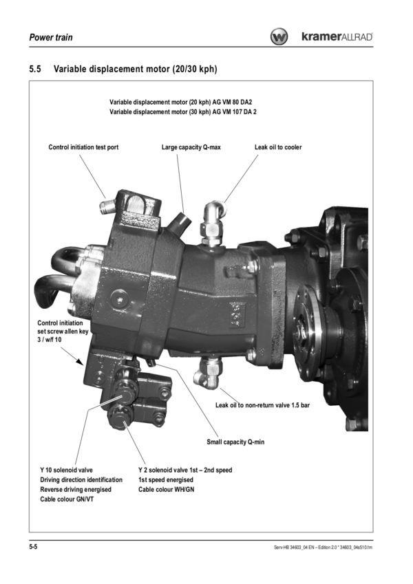
- Variable Displacement Motor (20/30 kph)
- Inching Valve Overview
- Inching Valve Circuit
- Inching Valve Diagram
- Drive Circuit
- Drive Diagram
- Towing and Transporting the Machine
- Test Report: 20 kph Power Train
- Test Report: 30 kph Power Train
- Adjustment Instructions
- Adjusting Boost Pressure
- Adjusting Starting Engine Speed and Control Pressure
- Setting High Pressure and Drive Pressure
- Setting the Secondary Valves for Forward and Reverse Driving
- Checking and Setting the Hydraulic Resistance of the Pump
- Checking Engine Droop
- Setting Control Initiation on the Variable Displacement Motor
- Setting the Wheel Speed
- Axles
- Axle Overview
- Front Axle Screw Connections
- Sealing Work on the Joint Housing and Axle Carrier
- Sealing the Rear Axle in Case of Oil Migration
- Assembly
- Setting the Gear Drive
- Removing the Gearbox
- Input Shaft Version 1 Sealing: Overview
- Assembling the Gearbox
- Brakes
- Brake Circuit
- Brake Diagram
- Parking Brake Circuit
- 20 kph Inching Valve Circuit
- Service Brake
- Steering System
- Steering Circuit
- Steering System Adjustment
- Hydraulic Ports on Servostat
- Pressure Relief Valve Adjustment
- Sealing Steering Rams
- Checking a Steering Ram
- Overview of Steering Ram Setting
- How to Check and Set the Steering Rams
- Checking the Track Setting
- Correcting the Track Setting
- Setting the Steering Limit
- Checking Steering Synchronisation
- Setting Steering Synchronisation
- Hydraulic System
- Work Hydraulics Test Report
- Work Hydraulics Oil Supply
- Control Valve Ports
- Priority Valve Ports
- Priority Valve Diagram
- Load Stabiliser Ports
- Load Stabiliser Circuit
- Load Stabiliser Diagram
- Lift Ram Sealing Work
- Tilt Ram Sealing Work
- Control Ram Sealing Work
- Work Hydraulics Diagram
- Hose Burst Valve Hydraulics Diagram (Option)
- Electrical System
- Ohm’s Law: Current, Voltage, Resistance and Power
- Measuring Equipment and Measuring Methods
- Terminal Description
- Colour Coding of Electric Lines
- Switching Relay Function
- Starter, Battery and Alternator
- Fuse Box
- Main Fuse Box with Relays
- Switching Relays
- Description of Blocking Diodes
- Overview of Switch Assignment
- Retrofitting a Rotating Beacon
- Retrofitting the Backup Warning System
- Retrofitting Two Front Working Lights
- Retrofitting Two Front Working Lights and One Rear Working Light
- Retrofitting Two Front Working Lights and Two Rear Working Lights
- Electric Diagram Legend
- Electric Diagram Sheet 1
- Electric Diagram Sheet 2
Be the first to review “Wacker Neuson 750, 850 Wheel Loader Service Repair Manual”
You must be logged in to post a review.
Reviews
There are no reviews yet.