

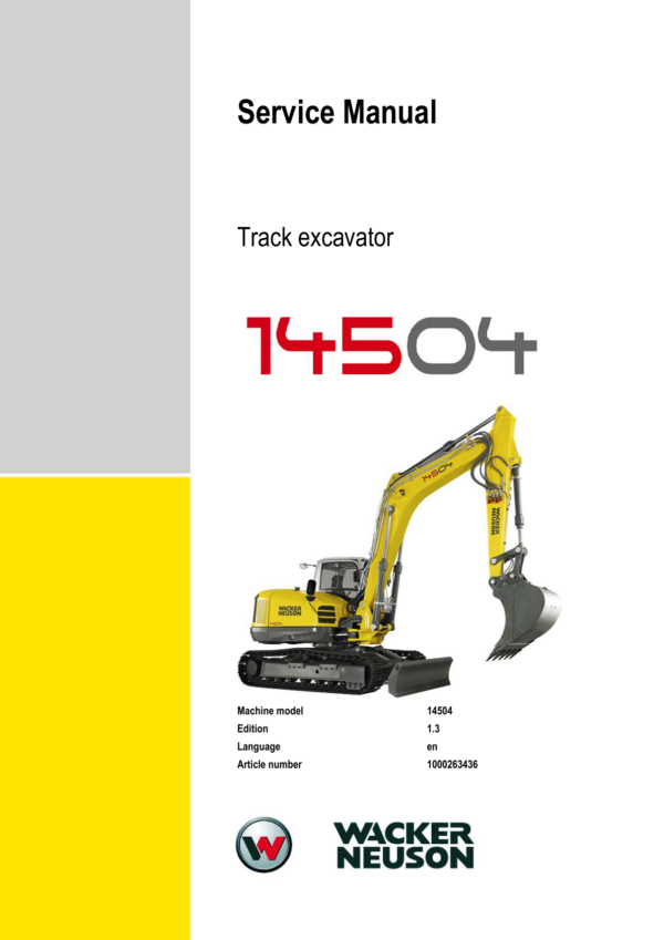
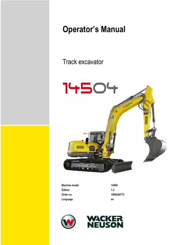
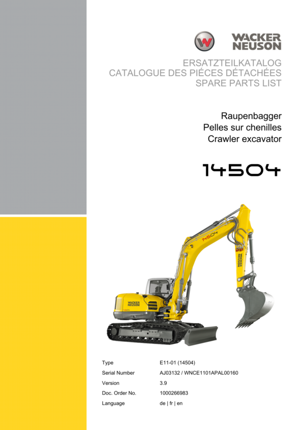
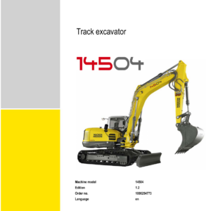
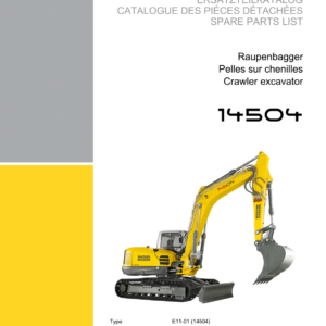
Wacker Neuson 14504 Excavator Service Repair Manual
$46.00
Manual Included:
- Service Repair Manual: 354 Pages
- Operators Manual: 202 Pages
- Spare Parts Catalog: 473 Pages
Specifications:
- Brand: Wacker Neuson
- Model: 14504
- Type: Track Excavator
- Manuals: Service Manual, Operators Manual, Spare Parts Catalog
- Language: English
- Format: PDF
- Description
- Reviews (0)
Description
Table of Content – Wacker Neuson 14504 Manual
- Operation
- Information on this service manual
- Abbreviations and symbols
- Identification of warnings and hazards
- Designated use and exclusion of liability
- Identification plates and machine numbers
- Machine overview
- Cabin overview
- Instrument panel overview
- Engine compartment overview
- Valve compartment overview
- Chassis section overview
- Technical Data
- Frame
- Engine
- Hydraulic system
- Travel drive and swing drive
- Dozer blade
- Electrical system
- Air conditioning
- Noise measurement
- Vibration
- Coolant mixing table
- Model-specific tightening torques
- General tightening torques
- Dimensions
- Payload, lifting capacity and lifting force
- Kinematics
- Maintenance
- Fluids and lubricants
- Maintenance label
- Maintenance plan
- Service package
- Safety-related components
- Fuel system
- Windshield washer reservoir
- Engine lubrication system
- Engine and hydraulic cooling system
- Air filter
- Cabin air filter
- V-belt
- Hydraulic system
- Pilot control filter
- Pressure check
- Travel drive
- Swing drive
- Tracks
- Electrical system
- Battery
- Air conditioning
- Diesel refueling pump
- General care and maintenance
- Lubrication points
- Preparing the machine for storage
- Maintenance during extended storage
- Returning the machine to operation
- Engine
- Engine TCD 2012 2V L04 overview
- Fuel system diagram
- Coolant system
- Valve cover removal
- Valve clearance inspection and adjustment
- Cylinder-head removal and installation
- Injection nozzle inspection and adjustment
- Injection spray inspection
- Injection timing
- Automatic engine speed control
- Compression pressure inspection
- Coolant thermostat inspection
- Coolant temperature sensor
- Oil pressure switch
- Coolant circuit inspection
- Engine troubleshooting
- Hydraulic System
- Valve compartment layout
- Engine compartment layout
- Cabin layout
- Hydraulic pump
- Variable double-pump unit
- Gear pump
- Proportional pressure-reducing valve
- Pump control
- Flow control
- Power control
- Negative control system
- Flow limitation
- Tightening torques
- Variable double-pump maintenance
- Pilot valves
- Valves
- Pilot oil unit
- Main control valve
- Components and valves
- Circulation system
- Negative control valve
- Main pressure relief valve
- Travel function
- Boom
- Stick
- Swing function
- Auxiliary control block supply
- Dozer blade control block
- Third control circuit and Powertilt control block
- Travel-straight signal valve block
- HSWS valve block
- Swing drive
- Swivel joint
- Travel drive
- Breather filter
- Overload warning device
- Hydraulic diagrams
- Electrical System
- Ohm’s Law and electrical power
- Measuring equipment and methods
- Cable color coding
- Relays
- Electrical components
- Cabin fuse box
- Main fuse box with relays
- Vehicle relays
- Cigarette lighter
- Power outlet
- Radio and radio preparation
- Instrument panel overview
- Control lever button assignments
- Alternator
- Starter
- Wiring diagrams
- Engine wiring harness
- Chassis wiring harness
- Cabin wiring harnesses
- Switch wiring harness
- Option cables and wiring harnesses
- Air Conditioning
- Specific safety instructions
- Technical data
- Installation overview
- Components
- Maintenance
- Options
- Automatic climate control
- Air-suspension operator seat
- Long stick
- Flat-face quick couplings
- Immobilizer
- Engine oil-pan service valve
- SAE and ISO control changeover valve
- Telematic system
- PowerTilt PTS10
- General information
- General safety instructions
- Product inspection
- Internal relief valve
- Machine hydraulic system test
- Specifications and requirements
- Tools
- Removing the bucket or attachment
- Removing the PowerTilt unit from the machine
- Exploded views
- Individual components
- Seal and bearing kits
- Assembly drawing
- Removing the standard pin coupler
- Removing the end cap and relief valve
- Removing the shaft
- Removing the piston tube assembly
- Removing and installing seals and bearings
- Installing the piston tube
- Installing the shaft
- Installing the end cap
- Installing the internal relief valve
- Installing the standard pin coupler
- Lubrication and testing
- Mounting the PowerTilt unit on the machine
- Mounting a bucket or attachment
- Troubleshooting
- Adjusting PowerTilt play
- HSWS OilQuick and Quicklock
- Safety instructions
- Technical data
- OilQuick quickhitch components
- H-cylinder
- Quicklock wiring harness
- Inspection and maintenance
- Quick coupling maintenance
- Attachment frame inspection
- Starting and stopping the excavator during maintenance
- Troubleshooting
- Operating Malfunctions
- Engine malfunctions
- Hydraulic malfunctions
- Swing drive malfunctions
- Air conditioning malfunctions
- Compressor troubleshooting
- Refueling pump error codes
- Refueling pump malfunctions
Be the first to review “Wacker Neuson 14504 Excavator Service Repair Manual”
You must be logged in to post a review.
Reviews
There are no reviews yet.