
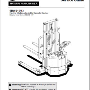
Toyota 6BWS10, 6BWS13 Electric Walkie Adjustable Straddle Stacker Repair Manual
$31.00
Format: PDF
Language: English
Model Covered: 6BWS10, 6BWS13
- Toyota 6BWS10, 6BWS13 Electric Walkie Adjustable Straddle Stacker Repair Manual – 102 Pages
- Wiring Diagram Manual – 11 Pages
- Description
- Reviews (0)
Description
Toyota 6BWS10, 6BWS13 Electric Walkie Adjustable Straddle Stacker Repair Manual
Format: PDF
Language: English
Model Covered: 6BWS10, 6BWS13
- Toyota 6BWS10, 6BWS13 Electric Walkie Adjustable Straddle Stacker Repair Manual – 102 Pages
- Wiring Diagram Manual – 11 Pages
This manual covers the inspection, adjustment and repair procedures mainly for the overhaul of the engine, chassis and material handling system of the Toyota 6BWS10, 6BWS13 Electric Stacker .
This repair manual contains the latest information available. Please under-stand that disagreement can take place between the descriptions in the manual and actual vehicles due to change in design and specifications. Any change or modifications thereafter will be informed by Toyota Industrial Equipment Parts & Service News.
For the service procedures of the mounted engine, read the repair manuals listed below as reference together with this manual.
Table of content of the Toyota 6BWS10, 6BWS13 Electric Stacker Manual
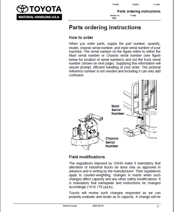
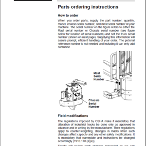
Parts ordering instructions ……………………………………………………………….. 5
Technical Data ………………………………………………………………………………….. 7
Introduction, Maintenance ……………………………………………………………….. 11
Service Program …………………………………………………………………………… 13
Cleaning and Washing …………………………………………………………………… 14
External Cleaning ………………………………………………………………………. 14
Motor Compartment Cleaning ……………………………………………………… 15
Electrical Components ……………………………………………………………….. 15
Safe Jacking ………………………………………………………………………………… 16
Planned Maintenance ………………………………………………………………………. 17
Maintenance Schedule ………………………………………………………………….. 17
Lubrication Schedule …………………………………………………………………….. 22
Oil and Grease Specification ……………………………………………………………. 23
Tools ……………………………………………………………………………………………….. 25
Super Seal Connectors ………………………………………………………………….. 25
AMP Connectors ……………………………………………………………………….. 26
Other Tools ………………………………………………………………………………. 27
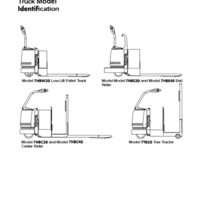
Support Arm Chassis ………………………………………………………………………. 29
General ……………………………………………………………………………………….. 29
Main Components …………………………………………………………………………. 30
Maintenance ………………………………………………………………………………… 30
Support Arm Width Adjustment ………………………………………………………. 31
Support Arm Replacement …………………………………………………………….. 32
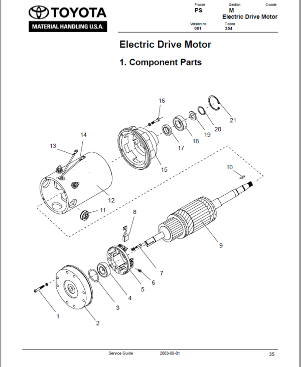
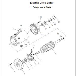
Electric Drive Motor …………………………………………………………………………. 35
Component Parts ………………………………………………………………………….. 35
Motor Dismantling from Truck ……………………………………………………… 37
Assembling ……………………………………………………………………………….. 37
Service/Repairs ……………………………………………………………………………. 38
Motor Dismantling ……………………………………………………………………… 38
Motor Assembling ……………………………………………………………………… 39
Cleaning …………………………………………………………………………………… 39
Technical Data ……………………………………………………………………………… 40
Drive Unit/Gear ………………………………………………………………………………… 41
Component Parts ………………………………………………………………………….. 42
Technical Data ………………………………………………………………………….. 44
Top Cover Leakage ………………………………………………………………………. 44
Drive Shaft Sealing Ring Replacement ……………………………………………. 45
Electromagnetic Brake …………………………………………………………………….. 47
Brake Main Components ……………………………………………………………….. 47
Maintenance ………………………………………………………………………………… 48
Basic Gap Adjustment ………………………………………………………………… 48
Brake Disc Replacement …………………………………………………………….. 49
Steering …………………………………………………………………………………………… 51
Component Parts, Steering (Tiller) Arm ……………………………………………. 51
Brake Microswitch Adjustments ………………………………………………………. 52
Steering (Tiller) Arm Handle …………………………………………………………… 53
Dismantling/Assembling ……………………………………………………………… 55
Electrical Systems …………………………………………………………………………… 57
Electrical Parts ……………………………………………………………………………… 57
List of Symbols and Electrical Wiring Diagram ………………………………….. 59
Electrical Diagram 1(6) ……………………………………………………………….. 61
Electrical Diagram 2(6) ……………………………………………………………….. 62
Electrical Diagram 3(6) ……………………………………………………………….. 63
Electrical Diagram 4(6) ……………………………………………………………….. 64
Electrical Diagram 5(6) ……………………………………………………………….. 65
Electrical Diagram 6(6) ……………………………………………………………….. 66
Functional Description …………………………………………………………………… 67
Starting the Truck ………………………………………………………………………. 67
Driving ……………………………………………………………………………………… 67
Neutral Speed Reduction ……………………………………………………………. 67
Picture 3 …………………………………………………………………………………… 67
Neutral Speed Reduction on Slopes …………………………………………….. 68
Braking …………………………………………………………………………………….. 68
Forks Lifting ………………………………………………………………………………. 68
Forks Lowering ………………………………………………………………………….. 68
Horn ………………………………………………………………………………………… 68
Hour Meter …………………………………………………………………………………… 69
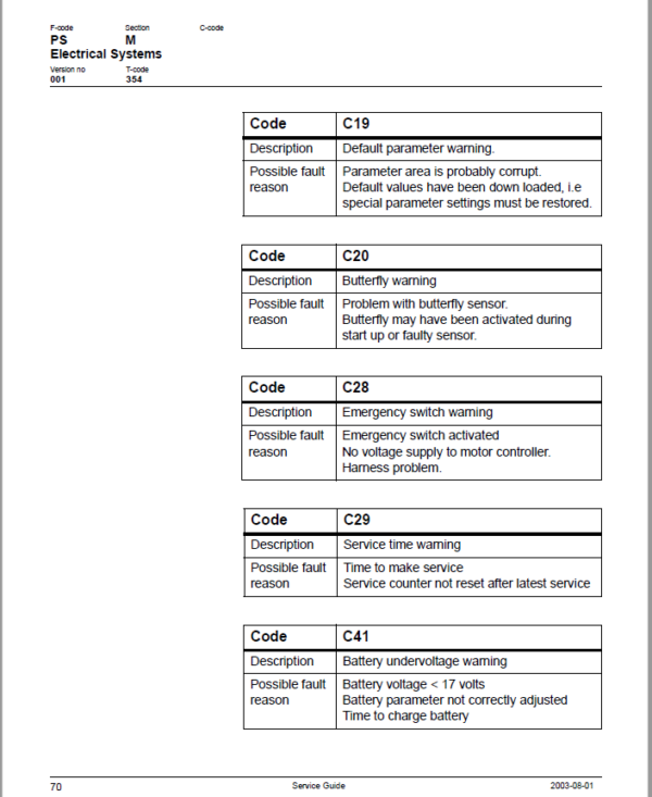
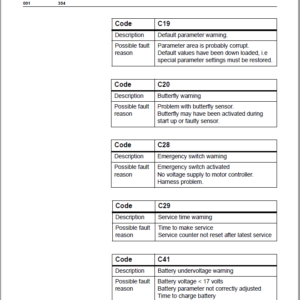
Fault Codes …………………………………………………………………………………. 69
Parameters ………………………………………………………………………………….. 75
Driver Parameters ……………………………………………………………………… 76
Service Parameters ……………………………………………………………………. 77
Parameter Description ……………………………………………………………….. 78
Part Numbers ……………………………………………………………………………….. 84
Transistor Panel ……………………………………………………………………………. 85
General ……………………………………………………………………………………. 85
Diagnostic and Troubleshooting ……………………………………………………… 86
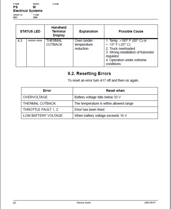
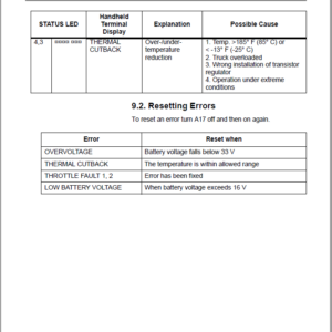
Error Codes and Troubleshooting ………………………………………………… 86
Resetting Errors ………………………………………………………………………… 87
Technical Specifications – Curtis 1243 …………………………………………….. 88
Hydraulic System …………………………………………………………………………….. 89
Hydraulic Diagram and Components ……………………………………………….. 89
Main Components ……………………………………………………………………… 90
Description ……………………………………………………………………………….. 90
Main lift chain system ………………………………………………………………………. 91
Checking the chain settings ……………………………………………………………. 91
Chain inspection …………………………………………………………………………… 91
Noise ……………………………………………………………………………………….. 91
Surface rust ………………………………………………………………………………. 91
Rusty links ………………………………………………………………………………… 91
Stiff links …………………………………………………………………………………… 92
Pin rotation ……………………………………………………………………………….. 92
Loose pins ………………………………………………………………………………… 92
Outline wear ……………………………………………………………………………… 93
Stretching …………………………………………………………………………………. 94
Damage ……………………………………………………………………………………. 95
Damaged discs …………………………………………………………………………. 95
Damaged pins …………………………………………………………………………… 95
Dirty chain ………………………………………………………………………………… 95
Cleaning ………………………………………………………………………………………. 96
Lubrication …………………………………………………………………………………… 96
Be the first to review “Toyota 6BWS10, 6BWS13 Electric Walkie Adjustable Straddle Stacker Repair Manual”
You must be logged in to post a review.

Reviews
There are no reviews yet.