
Toro Sand Pro 3040, 5040 (Models 08743, 08745) Service Repair Manual
$30.00
Manual Included:
- Service Repair Manual: 260 Pages
Specifications:
- Brand: Toro
- Model: Sand Pro 3040, 5040 (Models 08743, 08745)
- Type: Specialty Equipment
- Manuals: Service Repair Manual
- Publication Numbers: 20251SL
- Language: English
- Format: PDF
- Description
- Reviews (0)
Description
Table of Content – Sand Pro 3040, 5040 (Models 08743, 08745)
- Title Page
- Revision History
- Reader Comments
- Preface
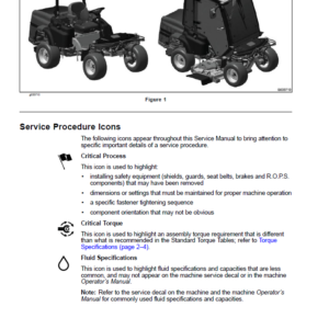
- Service Procedure Icons
- Chapter 1 : Safety
- Safety Instructions
- Think Safety First
- Jacking Instructions
- Safety and Instructional Decals
- Chapter 2 : Specifications and Maintenance
- Specifications
- Overall Dimensions
- Engine Specifications (Model 08743)
- Engine Specifications (Model 08745)
- Hydraulic System Specifications
- Chassis Specifications
- Torque Specifications
- Calculating the Torque Values When Using a Drive-Adapter Wrench
- Identifying the Fastener
- Standard Torque for Dry, Zinc Plated, and Steel Fasteners (Inch)
- Standard Torque for Dry, Zinc Plated, and Steel Fasteners (Metric Fasteners)
- Other Torque Specifications
- Conversion Factors
- Shop Supplies
- Special Tools
- Chapter 3 : Troubleshooting
- GEARS – The Systematic Approach to Defining, Diagnosing and Solving Problems
- Troubleshooting – Hydraulic
- General Hydraulic System Problems
- Traction System Problems
- Steering System Problems (Model 08745 Only)
- Attachment Lift, Lower Problems
- Attachment Hydraulic Problems
- Troubleshooting – Electrical
- Starting Problems
- General Run Problems
- Attachment Electrical Problems
- Chapter 4 : Engine
- General Information
- Traction Unit Operator’s Manual
- Briggs & Stratton Service Repair Manual
- Fuel Shut-Off Valve
- Adjustments
- Adjusting the Engine Controls
- Service and Repairs
- Cooling System
- Air Cleaner Assembly
- Fuel System
- Engine
- Briggs & Stratton V-Twin Engine Service Repair Manual
- Chapter 5 : Hydraulic System
- General Information
- Traction Unit Operator’s Manual and Accessory Installation Instructions
- Relieving Pressure from the Hydraulic System
- Towing the Traction Unit
- Traction Circuit Component Failure
- Hydraulic Hoses
- Installing Hydraulic Hoses and Tubes (O-Ring Face Seal Fitting)
- Installing the Hydraulic Fittings (SAE Straight Thread O-Ring Fittings)
- Hydraulic Schematics
- Hydraulic Flow Diagrams
- Traction Circuit
- Steering Circuit (Model 08745)
- Lift Circuit
- Rear Remote Hydraulic Circuit (Optional)
- Switch Kit Hydraulic Circuit (Optional)
- Testing the Hydraulic System
- Hydraulic Test Selection
- Testing the Traction Circuit – Charge Pressure
- Testing the Traction Circuit – Wheel Motor Efficiency
- Testing the Traction Circuit – Traction Pump (P1) Flow and Relief Pressure
- Testing the Lift and Steering Circuit – Implement, Charge Pump (P2) Flow and Circuit Relief
- Testing the Steering Circuit (Model 08745 only) – Steering Cylinder Internal Leakage
- Testing the Lift Circuit – Lift Cylinder Internal Leakage
- Testing the Optional Attachment Circuit – Attachment Pump (P3) Flow and Circuit Relief
- Adjustments
- Adjusting the Traction System for Neutral
- Service and Repairs
- General Precautions for Removing and Installing the Hydraulic System Components
- Checking the Hydraulic Lines and Hoses
- Flushing the Hydraulic System
- Filtering the Closed-loop Traction Circuit
- Priming the Hydraulic Pumps
- Charging the Hydraulic System
- Hydraulic Tank
- Hydraulic Fluid Cooler
- Piston (traction) Pump
- Servicing the Piston (traction) Pump
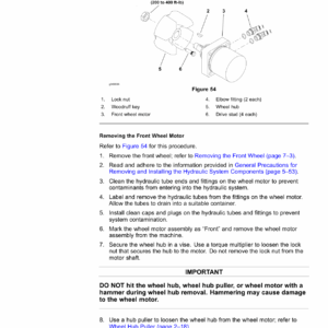
- Wheel Motors
- Servicing the Wheel Motors
- Traction Relief Manifold
- Rear Lift Relief Manifold (Model 08743)
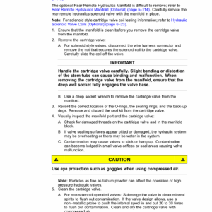
- Servicing a Hydraulic Cartridge Valve
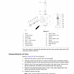
- Lift Control Valve
- Servicing the Lift Control Valve
- Rear Lift Cylinder
- Servicing the Rear Lift Cylinder
- Steering Control Valve (Model 08745)
- Servicing the Steering Control Valve (Model 08745)
- Steering Cylinder (Model 08745)
- Servicing the Steering Cylinder (Model 08745)
- Front Lift Cylinder (Optional)
- Servicing the Front Lift Cylinder (Optional)
- Rear Remote Hydraulics (Optional) or Switch Kit (Optional) Hydraulic Pump
- Servicing the Optional Rear Remote Hydraulics or Optional Switch Kit Hydraulic Pump
- Rear Remote Hydraulics Manifold (Optional)
- Hydraulic Switch Kit Manifold (Optional)
- Servicing the Optional Hydraulic Switch Kit Manifold
- Danfoss DDC20 Axial Piston Pump Service Repair Manual
- Parker Torqmotor™ Service Procedure (TF, TG, TH, and TL Series)
- Danfoss OSPM Steering Unit Service Repair Manual
- Parker PGP, PGM 500 Series Service Repair Manual
- Chapter 6 : Electrical System
- General Information
- Traction Unit Operator’s Manual and Accessory Installation Instructions
- Electrical Schematics and Wire Harness Drawings, Diagrams
- Electrical System Quick Checks
- Testing the Charging System
- Checking the Operation of the Safety Interlock Switches
- Testing the Electrical Components
- Fusible Links
- Fuses
- Key Switch
- Starter Solenoid
- Hour Meter
- Seat Switch
- Traction Neutral Switch
- Relays with 5 Terminals
- Diode Assemblies
- Hydraulic Solenoid Valve Coils (Optional)
- PTO Switch (Optional)
- Mode Select Switch (Optional)
- Light Switch (Optional)
- Service and Repairs
- Caring for the Battery
- Storing the Battery
- Servicing the Battery
- Chapter 7 : Chassis
- General Information
- Traction Unit Operator’s Manual and Accessory Installation Instructions
- Service and Repairs
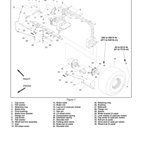
- Wheels
- Parking Brake
- Traction Pedal and Control Assembly
- Steering Wheel
- Steering Gear Box (Model 08743)
- Servicing the Steering Gear Box (Model 08743)
- Front Fork
- Hitch Assembly
- Operator’s Console
- Operator Seat
- Appendix A: Foldout Drawings
- Electrical Drawing Designations
- Hydraulic Schematic – Sand Pro 3040
- Hydraulic Schematic – Sand Pro 5040
- Electrical Schematic – Sand Pro 3040, 5040
- Wire Harness Drawing – Sand Pro 3040, 5040
- Wire Harness Diagram – Sand Pro 3040, 5040
- Wire Harness – Rear Remote Hydraulics (Optional)
- Wire Harness – Switch Kit (Optional)
Be the first to review “Toro Sand Pro 3040, 5040 (Models 08743, 08745) Service Repair Manual”
You must be logged in to post a review.
Reviews
There are no reviews yet.