
Toro Reelmaster 7000 (Models 03780, 03781) Service Repair Manual
$34.00
Manual Included:
- Service Repair Manual: 468 Pages
Specifications:
- Brand: Toro
- Model: Reelmaster 7000 (Models 03780, 03781)
- Type: Large Reel Mowers
- Manuals: Service Repair Manual
- Publication Numbers: 15214SL
- Language: English
- Format: PDF
- Description
- Reviews (0)
Description
Table of Content – Reelmaster 7000 (Models 03780, 03781)
- Title Page
- Revision History
- Reader Comments
- Preface
- Table of Contents
- 1 – Safety
- General Safety Instructions
- Before Operating
- While Operating
- Maintenance and Service
- Jacking Instructions
- Safety and Instruction Decals
- 2 – Product Records and Maintenance
- Product Records
- Maintenance
- Equivalents and Conversions
- Torque Specifications
- Fastener Identification
- Using a Torque Wrench with an Offset Wrench
- Standard Torque for Dry, Zinc Plated and Steel Fasteners (Inch Series)
- Standard Torque for Dry, Zinc Plated and Steel Fasteners (Metric Series)
- Conversion Factors
- 3 – Yanmar Diesel Engine
- Specifications
- General Information
- Operator's Manuals
- Yanmar Service and Troubleshooting Manuals
- Stopping the Engine
- Engine Electronic Control Unit (ECU)
- Yanmar Engine
- Service and Repairs
- Air Cleaner System
- Exhaust System
- Fuel System
- Radiator, Hydraulic Oil Cooler
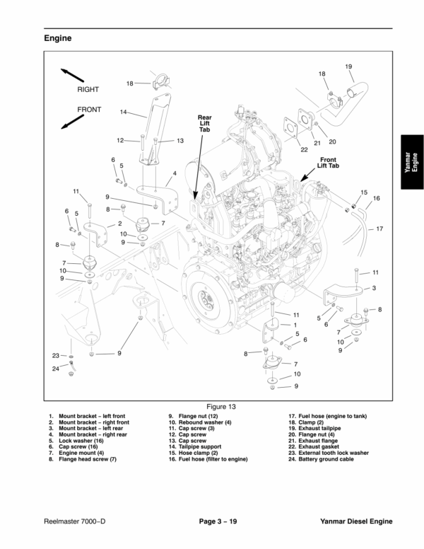
- Engine
- Pump Adapter Plate
- YANMAR TNV (Tier 4) SERIES Service Repair Manual
- YANMAR TNV (Tier 4) SERIES TROUBLESHOOTING MANUAL
- 4 – Kubota Diesel Engine
- Specifications
- General Information
- Operator's Manual
- Service and Repairs
- Air Filter System
- Exhaust System
- Fuel System
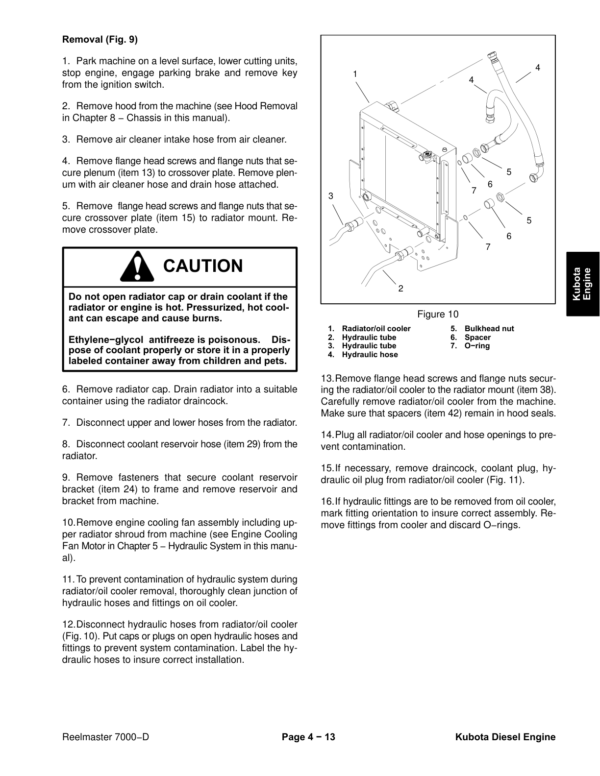
- Radiator, Hydraulic Oil Cooler
- Engine
- Pump Adapter Plate
- KUBOTA WORKSHOP MANUAL DIESEL ENGINE 03−M−DI−E3B SERIES
- 5 – Hydraulic System
- Specifications
- General Information
- Operator's Manual
- Hydraulic Component Locations
- Relieving Hydraulic System Pressure
- Traction Circuit Component Failure
- Towing Traction Unit
- Hydraulic Hoses
- Hydraulic Hose and Tube Installation (O-Ring Face Seal Fitting)
- Hydraulic Fitting Installation (SAE Straight Thread O-Ring Fitting into Component Port)
- Hydraulic Schematic
- Hydraulic Flow Diagrams
- Traction Circuit: LOW Speed (Mow)
- Traction Circuit: HI Speed (Transport)
- Mow Circuit
- Steering Circuit
- Lower Cutting Units
- Raise Cutting Units
- Engine Cooling Fan Circuit
- Special Tools
- Hydraulic Pressure Test Kit
- Hydraulic Tester (Pressure and Flow)
- 40 GPM Hydraulic Tester (Pressure and Flow)
- Hydraulic Hose Kit
- High Flow Hydraulic Filter Kit
- Hydraulic Test Fitting Kit
- Measuring Container
- O-ring Kit
- Remote Starter Switch
- Troubleshooting
- General Hydraulic System Problems
- Traction Circuit Problems
- Mow Circuit Problems
- Steering Circuit Problems
- Lift, Lower Circuit Problems
- Engine Cooling Fan Circuit Problems
- Testing
- Traction Circuit – Charge Pressure Test
- Traction Circuit – Relief Pressure Test
- Traction Circuit – Piston (traction) Pump Flow Test
- Traction Circuit – Front Wheel Motor Case Drain Leakage Test
- Traction Circuit – Reverse Reducing Valve (PR) Pressure Test
- Traction Circuit – Rear Relief Valve (RV) Pressure Test
- Cutting Unit Circuit – Pressure Test
- Cutting Unit Circuit – Relief Pressure Test
- Cutting Unit Circuit – Cutting Unit Motor Case Drain Leakage Test
- Steering, Lift Circuit – Steering Relief Pressure Test
- Steering, Lift Circuit – Steering Cylinder Test
- Steering, Lift Circuit – Lift Relief Pressure Test
- Cooling Fan Circuit – Pressure Test
- Cooling Fan Circuit – Fan Motor Case Drain Leakage Test
- Gear Pump Flow Test (pump sections P2 thru P5)
- Adjustments
- Control Manifold Relief Valve Adjustment
- Service and Repairs
- General Precautions for Removing and Installing Hydraulic System Components
- Check Hydraulic Lines and Hoses
- Priming Hydraulic Pumps
- Flush Hydraulic System
- Filtering Closed-Loop Traction Circuit
- Charge Hydraulic System
- Gear Pump
- Gear Pump Service
- Piston (Traction) Pump
- Piston (traction) Pump Service
- Rear Traction Manifold
- Rear Traction Manifold Service
- HI, LOW Range Manifold
- Front Wheel Motors
- Rear Axle Motor
- Front Wheel Motor and Rear Axle Motor Service
- Cutting Unit Motor
- Cutting Unit Motor Service
- Mow Control Manifold
- Mow Control Manifold Service
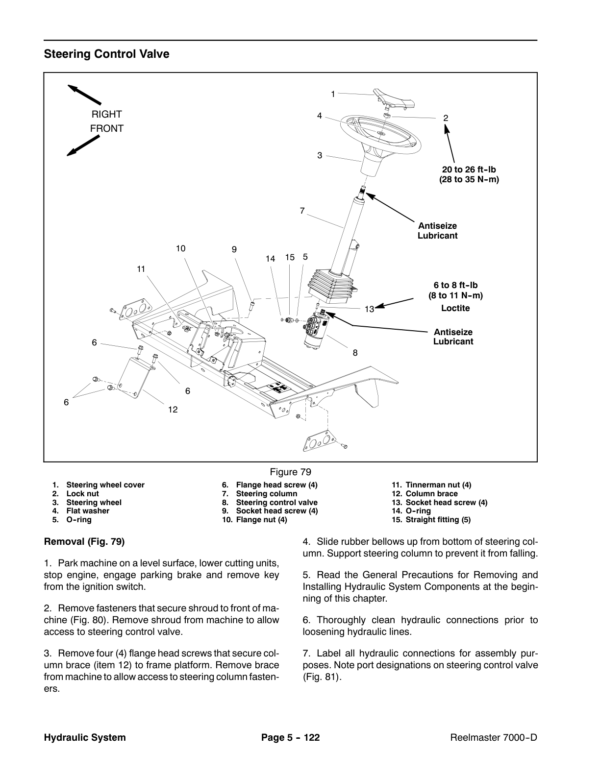
- Steering Control Valve
- Steering Control Valve Service
- Steering Cylinder
- Steering Cylinder Service
- Engine Cooling Fan Motor
- Engine Cooling Fan Motor Service
- Fan Control Manifold
- Fan Control Manifold Service
- Lift Manifold
- Lift Manifold Service
- Control Manifold Cartridge Valve Service
- Lift Junction Manifold
- Front Lift Cylinders
- Rear Lift Cylinders
- Lift Cylinder Service
- Hydraulic Reservoir
- Hydraulic Oil Cooler
- EATON MODEL 72400 SERVO CONTROLLED PISTON PUMP REPAIR INFORMATION
- DANFOSS K and L FRAME VARIABLE MOTORS Service Repair Manual
- DANFOSS STEERING UNIT TYPE OSPM Service Repair Manual
- 6 – Electrical System
- General Information
- Operator's Manual
- Toro Electronic Controller (TEC)
- Engine Electrical Components
- Engine Electronic Control Unit (ECU) (Yanmar Diesel Engines Only)
- CAN-bus Communications
- Electrical Drawings
- Special Tools
- Multimeter
- Dielectric Gel
- Battery Hydrometer
- Terminal Protector
- InfoCenter Display
- InfoCenter Display Screens
- Splash Screen
- Main Information Screen
- Operator Advisory Screen
- Main Menu Screen
- Faults Screen
- Service Screen
- Diagnostics Screen
- Settings Screen
- About Screen
- Troubleshooting
- Operator Advisories
- Using the InfoCenter Display for Troubleshooting
- Fault Codes
- Starting Problems
- General Run and Transport Problems
- Cutting Unit Operating Problems
- Cutting Unit Lift, Lower Problems
- Electrical System Quick Checks
- Battery Test (Open Circuit Test)
- Charging System Test
- Glow Plug System Test
- Check Operation of Interlock Switches
- Adjustments
- HI, LOW (transport, mow) Switch
- Cutting Unit Position Switch
- Component Testing
- Fusible Link Harness
- Fuses
- Toro Electronic Controllers (TEC)
- Ignition Switch
- Reel Enable, Disable Switch
- Engine Speed Switch (Yanmar Diesel Engine Only)
- Lower, Raise Joystick Switches
- Seat Switch
- Traction Neutral Switch
- Parking Brake Switch
- HI, LOW (Transport, Mow) Switch
- Cutting Unit Position Switch
- Backlap Switches
- Hydraulic Oil Temperature Sender
- Engine Temperature Sender (Kubota Diesel Engine Only)
- Relays with Four (4) Terminals
- Relays with Five (5) Terminals
- Hydraulic Solenoid Valve Coils
- Fuel Pump (Yanmar Diesel Engine Only)
- Fuel Pump (Kubota Diesel Engine Only)
- Fuel Stop Solenoid (Kubota Diesel Engines Only)
- CAN-bus Termination Resistor
- Diode Assembly
- Resistor Assembly
- Worklight Switch
- Service and Repairs
- Battery Storage
- Battery Care
- Battery Service
- Hydraulic Solenoid Valve Coils
- Worklight Bulb Replacement
- 7 – Axles, Planetaries and Brakes
- Table of Contents
- Specifications
- General Information
- Operator's Manual
- Adjustments
- Planetary Drive End Play (OPH-2 series planetary drives)
- Service and Repairs
- Brake Assembly
- Brake Inspection and Repair
- Planetary Drive Assembly
- OPH-2 Planetary Drive Service
- VA02 Series Planetary Drive Service
- Rear Axle Assembly
- Rear Axle Service
- Bevel Gear Case and Axle Case
- Differential Shafts
- Axle Shafts
- Input Shaft, Pinion Gear
- Differential Gear
- Pinion Gear to Ring Gear Engagement
- 8 – Chassis
- General Information
- Operator's Manual
- Cutting Unit Identification
- Service and Repairs
- Steering Column
- Console Arm
- Lift Arms for Front Cutting Units (#1, #4 and #5)
- Lift Arms for Rear Cutting Units (#2 and #3)
- Operator Seat
- Operator Seat Service
- Operator Seat Suspension
- Hood
- 9 – DPA Cutting Units
- Table of Contents
- Specifications
- General Information
- Cutting Unit Operator's Manual
- Special Tools
- Gauge Bar Assembly
- Bedknife Screw Tool
- Handle Assembly
- Plastic Plug
- Cutting Unit Kickstand
- Spline Insert Tool
- Diameter, Circumference Measuring Tape
- Roller Rebuild Kit
- Turf Evaluator Tool
- Reel Bearing Installation Tool (cutting units with painted side plates)
- Cutting Reel Shim
- Cutting Performance Paper
- Pulley Alignment Tool
- Bedknife Top Angle Indicator and Mount
- Factors That Can Affect Cutting Performance
- Adjustments
- Characteristics
- Reel Bearing Adjustment (cutting units with painted side plates)
- Leveling Rear Roller
- Service and Repairs
- Hydraulic Reel Motor
- Backlapping
- Bedbar Assembly
- Bedknife Replacement and Grinding
- Bedbar Adjuster Service
- Reel Assembly (cutting units with painted side plates)
- Reel Assembly Service (cutting units with painted side plates)
- Reel Assembly (cutting units with aluminum side plates)
- Reel Assembly Service (cutting units with aluminum side plates)
- Preparing Reel for Grinding
- Front Roller
- Rear Roller
- Roller Service
- Rear Roller Brush – Optional (cutting units with painted side plates)
- Rear Roller Brush – Optional (cutting units with aluminum side plates)
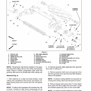
- 10 – Belt Driven Groomer (Optional)
- Table of Contents
- Grooming Performance
- Troubleshooting
- Groomer Reel Mechanical Problems
- Adjustments
- Groomer Height, Depth Adjustment
- Service and Repairs
- Groomer Drive Belt Replacement
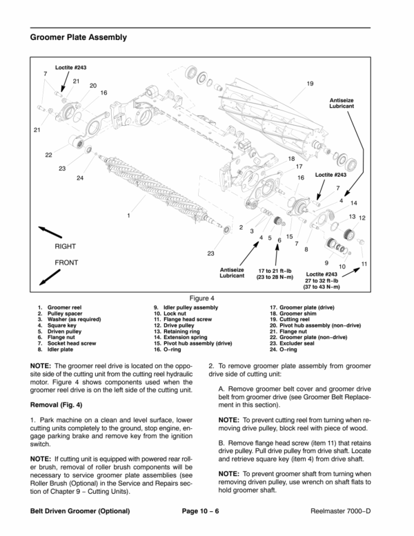
- Groomer Plate Assembly
- Groomer Reel
- Groomer Reel Service
- Groomer Pivot Hub
- Height Adjuster Assembly
- 11 – Universal Groomer (Optional)
- Table of Contents
- Grooming Performance
- Troubleshooting
- Groomer Reel Mechanical Problems
- Service and Repairs
- Gear Box Assembly
- Idler Assembly
- Groomer Reel
- Groomer Reel Service
- Grooming Brush (Optional) Service
- Height Adjuster Assembly
- 12 – Foldout Drawings
- Electrical Drawing Designations
- Hydraulic Schematic
- Electrical Schematic – Traction Unit Model 03780 – Yanmar Engine (Serial numbers below 316000000)
- Electrical Schematic — Traction UnitModel 03780 — Yanmar Engine(Serial numbers 316000001 to 403350000)
- Electrical Schematic — Traction UnitModel 03780 — Yanmar Engine(Serial numbers above 403350001)
- Electrical Schematic – Traction Unit Model 03781 – Kubota Engine (Serial numbers below 316000000)
- Electrical Schematic — Traction UnitModel 03781 — Kubota Engine(Serial numbers 316000001 to 403350000)
- Electrical Schematic — Traction UnitModel 03781 — Kubota Engine(Serial numbers above 403350001)
- Electrical Schematic – Cab
- Main Wire Harness Drawing (Serial numbers below 316000000)
- Main Wire Harness Diagram (Serial numbers below 316000000)
- Main Wire Harness DrawingModel 03780 & 03781(Serial numbers 316000001 to 403350000)
- Main Wire Harness DiagramModel 03780 & 03781(Serial numbers 316000001 to 403350000)
- Main Wire Harness DrawingModel 03780 & 03781(Serial numbers 403350001 to 405699999)
- Main Wire Harness DiagramModel 03780 & 03781(Serial numbers 403350001 to 405699999)
- Main Wire Harness DrawingModel 03780 & 03781(Serial numbers above 405700000)
- Main Wire Harness DiagramModel 03780 & 03781(Serial numbers above 405700000)
- Engine Wire Harness Drawing – Yanmar
- Engine Wire Harness Diagram – Yanmar
- Engine Wire Harness Drawing – Kubota
- Engine Wire Harness Diagram – Kubota
- Seat and Console Wire Harness Drawing
- Seat and Wire Harness Diagram
- Power Center Wire Harness Drawing (Serial numbers below 403350000)
- Power Center Wire Harness Diagram (Serial numbers below 403350000)
- Power Center Wire Harness DrawingModel 03780 & 03781(Serial numbers above 403350001)
- Power Center Wire Harness DiagramModel 03780 & 03781(Serial numbers above 403350001)
Be the first to review “Toro Reelmaster 7000 (Models 03780, 03781) Service Repair Manual”
You must be logged in to post a review.
Reviews
There are no reviews yet.