
Toro ProLine H800 (Model 31050, 31050TE, 31051) Service Repair Manual
$34.00
Manual Included:
- Service Repair Manual: 348 Pages
Specifications:
- Brand: Toro
- Model: ProLine H800 (Model 31050, 31050TE, 31051)
- Type: Rotary Mowers
- Manuals: Service Repair Manual
- Publication Numbers: 19241SL
- Language: English
- Format: PDF
- Description
- Reviews (0)
Description
Table of Content – ProLine H800 (Model 31050, 31050TE, 31051)
- Title Page
- Revision History
- Reader Comments
- Preface
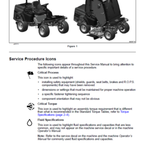
- Service Procedure Icons
- Table of Contents
- Chapter 1 : Safety
- Safety Instructions
- Supervisor’s Responsibilities
- Before Operating the Machine
- While Operating the Machine
- Maintenance and Service
- Jacking Instructions
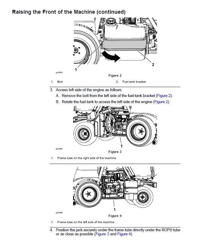
- Raising the Front of the Machine
- Raising the Rear of the Machine
- Safety and Instructional Decals
- Chapter 2 : Specifications and Maintenance
- Specifications
- Overall Dimensions
- Engine – ProLine H800 (for Model 31050)
- Engine – ProLine H800 (for Model 31050TE and 31051)
- Hydraulic System
- Chassis
- Torque Specifications
- Identifying the Fastener
- Calculating the Torque Values When Using a Drive-Adapter Wrench
- Standard Torque for Dry, Zinc Plated, and Steel Fasteners (Inch)
- Standard Torque for Dry, Zinc Plated, and Steel Fasteners (Metric Fasteners)
- Other Torque Specifications
- Conversion Factors
- Shop Supplies
- Special Tools
- Chapter 3 : Troubleshooting
- GEARS – The Systematic Approach to Defining, Diagnosing and Solving Problems
- General Hydraulic System Problems
- Steering Circuit Problems
- The Height Of Cut Circuit Problems
- The Cutting Deck Lift Circuit Problems
- The Hopper Lift Circuit
- The Hopper Tilt Circuit
- Chapter 4 : Engine
- General Information
- Traction Unit Operator’s Manual
- Yanmar Service Repair Manuals
- Service and Repairs
- Air Cleaner Assembly
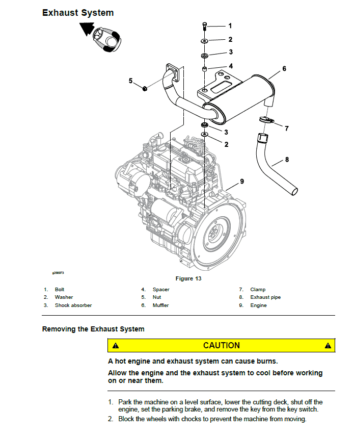
- Exhaust System
- Radiator
- Fuel System
- Engine
- Yanmar 3TNV76 Service Repair Manual
- Yanmar 3TNV80F Service Repair Manual
- Chapter 5 : Hydraulic System
- General Information
- Checking the Hydraulic Fluid
- Pushing or Towing the Traction Unit
- Releasing Pressure from the Hydraulic System
- Traction Circuit Component Failure
- Hydraulic Hoses
- Installing the Hydraulic Hoses and Tubes
- Installing the Hydraulic Fittings
- Hydraulic Schematic
- Hydraulic Flow Diagrams
- Traction Circuit
- Steering Circuit
- Height Of Cut Circuit
- Auxiliary Control Circuit
- Testing the Hydraulic System
- Testing the Traction Circuit – Charge Pressure
- Testing the Wheel Motors Efficiency
- Testing the Traction Circuit – Hydraulic Pump Flow and Relief Pressure
- Testing the Steering Circuit – Steering Control Valve, Relief Valve Pressure and Steering Cylinder
- Testing the Steering Circuit – Charge Pump Flow
- Testing the Auxiliary Control Circuit – Cutting Deck Lift Cylinder Internal Leakage
- Testing the Auxiliary Control Circuit – Hopper Lift Cylinder Internal Leakage
- Testing the Auxiliary Control Circuit – Hopper Tilt Cylinder Internal Leakage
- Testing the Height Of Cut Cylinder Internal Leakage
- Service and Repairs
- General Precautions for Removing and Installing the Hydraulic System Components
- Checking the Hydraulic Lines and Hoses
- Flushing the Hydraulic System
- Filtering the Closed-Loop Traction Circuit
- Priming the Hydraulic Pump
- Charging the Hydraulic System
- Hydraulic Tank
- Auxiliary Control Valve
- Traction Neutral Arm Assembly
- Hydraulic Pump Assembly
- Servicing the Hydraulic Piston Pump
- Servicing the Gear Pump
- Front Wheel Motors
- Rear Wheel Motors
- Servicing the Hydraulic Wheel Motor
- Differential Valve
- Height Of Cut Valve
- Lift Cylinder
- Steering Control Valve
- Steering Cylinder
- Hopper Lift Cylinder
- Hopper Tilt Cylinder
- Height Of Cut Cylinder
- Chute Cleaning Cylinder
- Oil Cooler
- Danfoss DDC20 Axial Piston Pump Service Repair Manual
- Parker Torqmotor Service Procedure (TF, TG, TH, and TL Series)
- Chapter 6 : Electrical System
- General Information
- Electrical Schematics and Wire Harness Drawings, Diagrams
- Electronic Control Unit (ECU)
- Electrical System Quick Checks
- Testing the Battery (Open Circuit Test)
- Testing the Charging System
- Testing the Glow Plug System
- Checking the Operation of the Interlock Switches
- Testing the Electrical Components
- Fuses
- Key Switch
- PTO Switch
- Hazard Light Switch
- Differential Lock Switch
- Radiator Fan Reversal Switch
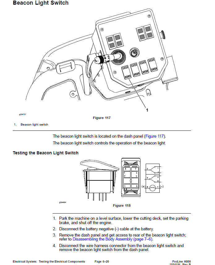
- Beacon Light Switch
- Indicator Lights
- Height Of Cut Switch
- Seat Switch
- Hour Meter
- Traction Neutral Switch
- Traction Reverse Switch
- Parking Brake Switch
- Oil Pressure Switch
- PTO Electric Clutch
- Fuel Stop Solenoid
- Relays
- Diode Assembly
- Slope Sensor (Optional)
- Service and Repairs
- Battery Storage
- Battery Care
- Servicing the Battery
- Chapter 7 : Chassis
- General Information
- Service and Repairs
- Wheels
- Body Assembly
- Steering Column
- Lift Arms
- Traction Pedal
- Brake Pedal
- Operator Seat
- Servicing the Operator Seat
- Frame Assembly
- Grammer Seats Repair Manual
- Chapter 8 : Axle and PTO
- General Information
- Service and Repairs
- Servicing the Brake
- Rear Axle assembly
- Servicing the Rear Axle
- Steering Spindle
- PTO Drive Belt
- Electric Clutch
- PTO Driveshaft
- Servicing the Driveshaft
- PTO Shaft Assembly
- Servicing the PTO Shaft Assembly
- Servicing the Gearbox Assembly
- Chapter 9 : Hopper Assembly
- General Information
- Service and Repairs
- Hopper Assembly
- Hopper Frame Assembly
- Hopper
- Hopper Lift Frame Assembly
- Chute Assembly
- Chapter 10 : Cutting Unit
- General Information
- Service and Repairs
- Idler Assembly
- Blade Spindle
- Servicing the Blade Spindle
- Caster Wheel and Flat Frame Assembly
- Cutting Deck Rollers and Skids
- Height Of Cut Linkage
- Cutting Deck Covers
- Appendix A: Foldout Drawings
- Electrical Drawing Designations
- Hydraulic Schematic
- Electrical Schematic – Main
- Electrical Schematic – Lights
- Wire Harness Diagram – Main
- Wire Harness Diagram – Lights
- Wire Harness – Slope Sensor (Optional)
Be the first to review “Toro ProLine H800 (Model 31050, 31050TE, 31051) Service Repair Manual”
You must be logged in to post a review.


Reviews
There are no reviews yet.