 Service Repair Manual")
Toro Groundsmaster 5900, 5910 (Models 31598, 31599) Service Repair Manual
$34.00
Manual Included:
- Service Repair Manual: 561 Pages
Specifications:
- Brand: Toro
- Model: Groundsmaster 5900, 5910 (Models 31598, 31599)
- Type: Rotary Mowers
- Manuals: Service Repair Manual
- Publication Numbers: 08159SL
- Language: English
- Format: PDF
- Description
- Reviews (0)
Description
Table of Content – Groundsmaster 5900, 5910 (Models 31598, 31599)
- Title Page
- Revision History
- Reader Comments
- Notes:
- Preface
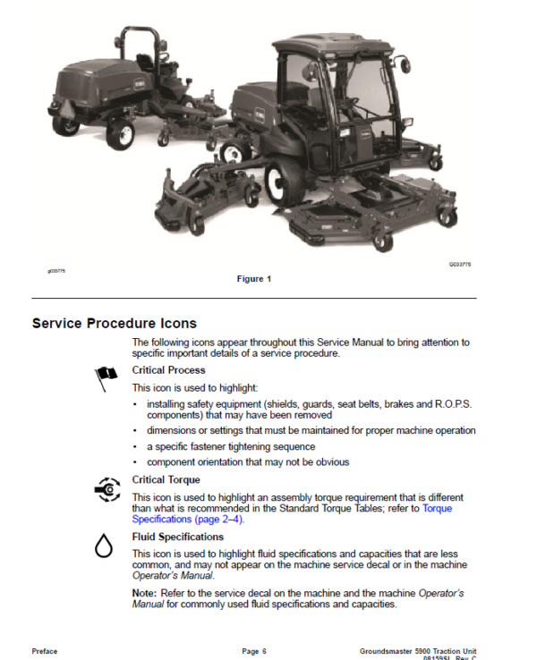
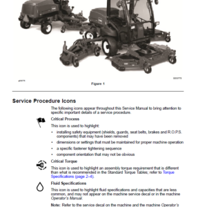
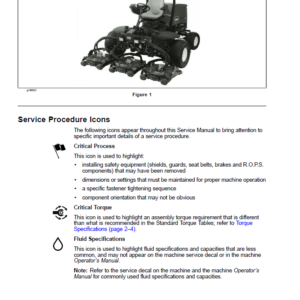
- Service Procedure Icons
- Table of Contents
- Chapter 1 : Safety
- Safety Instructions
- Before Operating the Machine
- While Operating the Machine
- Maintenance and Service
- Jacking Instructions
- Raising the Front of the Machine
- Raising the Rear of the Machine
- Safety and Instructional Decals
- Chapter 2 : Specifications and Maintenance
- Specifications
- Decimal and Millimeter Equivalents
- U.S. to Metric Conversions
- Torque Specifications
- Identifying the Fastener
- Calculating the Torque Values When Using a Drive-Adapter Wrench
- Standard Torque for Dry, Zinc Plated, and Steel Fasteners (Inch Series)
- Standard Torque for Dry, Zinc Plated, and Steel Fasteners (Metric Series)
- Other Torque Specifications
- Conversion Factors
- Shop Supplies
- Special Tools
- Chapter 3 : Diesel Engine
- 1 Specifications
- Diesel Engine
- General Information
- Operator’s Manual
- Engine Identification
- Engine Electronic Control Module (ECM)
- Shutting Off the Engine
- Fuel-Injection System
- Adjustments
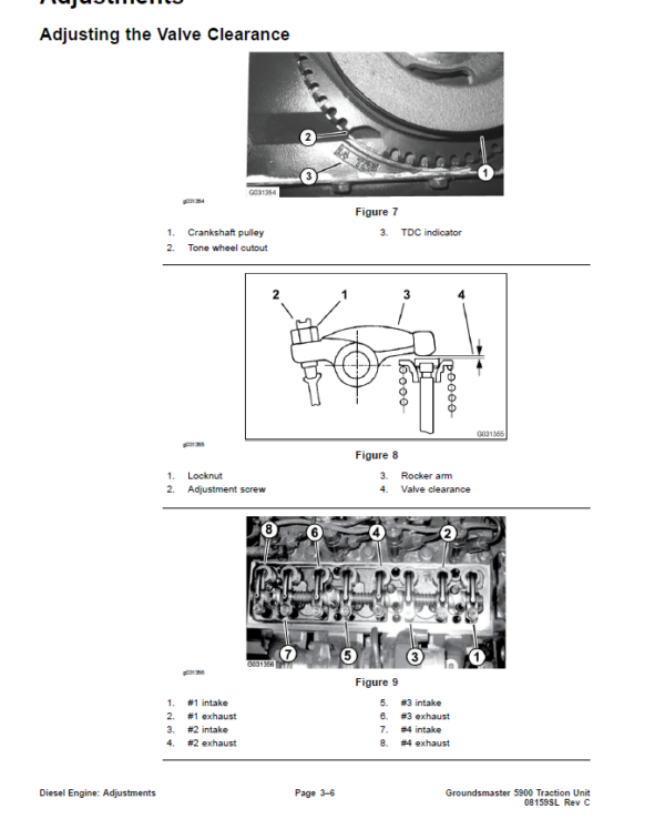
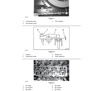
- Adjusting the Valve Clearance
- Service and Repairs
- Air Filter System
- Exhaust System
- Turbocharger
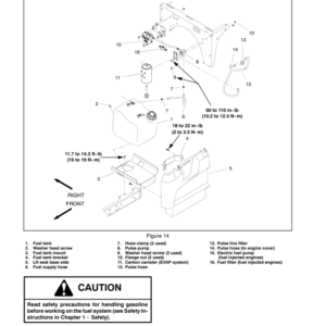
- Fuel Tank
- Radiator
- Alternator
- Starter Motor
- Valve Cover
- Engine Breather System
- Thermostat
- Water Pump
- Front Cover
- Oil Pan
- Engine
- Flywheel Coupling Assembly
- Chapter 4 : Hydraulic System
- 1 Specifications
- Hydraulic System
- General Information
- Checking the Hydraulic Fluid
- Releasing Pressure from the Hydraulic System
- Towing the Traction Unit
- Traction Circuit Component Failure
- Hydraulic Hoses
- Installing the Hydraulic Hose and Tube (O-Ring Face Seal Fitting)
- Installing the Hydraulic Fittings (SAE Straight Thread O-Ring Fitting into the Component Port)
- Hydraulic Schematic
- Hydraulic Flow Diagrams
- Traction Circuit: Low Speed
- Traction Circuit: High Speed
- Traction Circuit: Traction Control
- Raising the Cutting Deck
- Lowering the Cutting Deck
- PTO Mow Circuit
- Steering Circuit
- Engine Cooling Fan Circuit
- Special Tools
- Hydraulic Pressure Testing Kit
- 15 GPM Hydraulic Tester (Pressure and Flow)
- 40 GPM Hydraulic Tester (Pressure and Flow)
- Hydraulic Hose Kit
- High Flow Hydraulic Filter Kit
- O-Ring Kit
- Hydraulic Test Fitting Kit
- Measuring Container
- Rear Wheel Hub Puller
- Troubleshooting
- General Hydraulic System Problems
- Traction Problems
- PTO Problems
- Steering Circuit Problems
- Lift, Lower Problem
- Testing the Hydraulic System
- Determining which Hydraulic Tests to Perform
- Testing the Traction Circuit Charge Pressure (Using Pressure Gauge)
- Testing the Traction Circuit Relief Pressure (Using Pressure Gauge)
- Testing the Rear Traction Circuit (RV) Relief Pressure (Using Pressure Gauge)
- Testing the Traction Circuit Reducing Valve (PR) Pressure (Using Pressure Gauge)
- Testing the Counterbalance Pressure (Using Pressure Gauge)
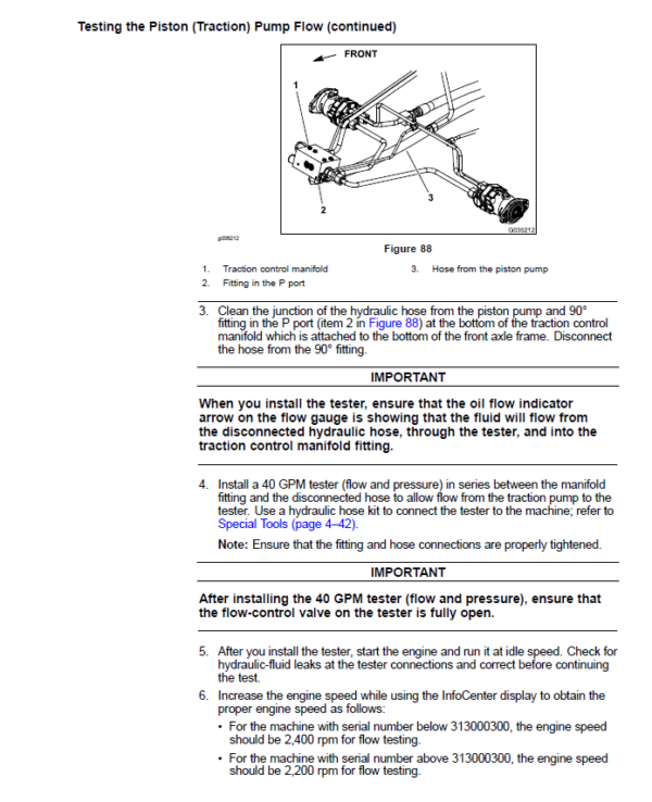
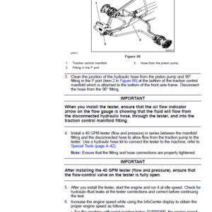
- Testing the Piston (Traction) Pump Flow (Using Tester with Pressure Gauge and 40 GPM Flow Meter)
- Testing the Cutting Deck Circuit Pressure (Using Pressure Gauge)
- Testing the Cutting Deck Circuit Relief Pressure (Using Tester with Pressure Gauge and 40 GPM Flow Meter)
- Testing the Cutting Deck Motor for Case Drain Leakage (Using Tester with Pressure Gauge and 40 GPM Flow Meter)
- Testing the Lift, Lower Circuit Relief Pressure (Using Pressure Gauge)
- Testing the Steering Circuit Relief Pressure (Using Pressure Gauge)
- Testing the Steering Cylinder for Internal Leakage
- Testing the Gear Pump (P3) (PTO, Steering, Cooling Fan, Lift, Lower, and Traction Charge Circuits) Flow (Using Tester with Pressure Gauges and Flow Meter)
- Adjustments
- Adjusting the Pressure Valve
- Service and Repairs
- General Precautions for Removing and Installing the Hydraulic System Components
- Checking the Hydraulic Lines and Hoses
- Flushing the Hydraulic System
- Charging the Hydraulic System
- Filtering the Closed-Loop Traction Circuit
- Hydraulic Reservoir
- Gear Pump
- Servicing the Gear Pump
- Traction Circuit
- Piston (Traction) Pump
- Servicing the Piston (Traction) Pump (Rexroth)
- Servicing the Piston (Traction) Pump (Sauer-Danfoss)
- Front Wheel Motors
- Servicing the Front Wheel Motor
- Rear Wheel Motors
- Servicing the Rear Wheel Motor
- Traction Control Manifold
- Servicing the Traction Control Manifold
- 4-Wheel Drive Control Manifold
- Servicing the 4-Wheel Drive Control Manifold
- Traction Flush Manifold
- PTO Circuit
- Cutting Deck Motor
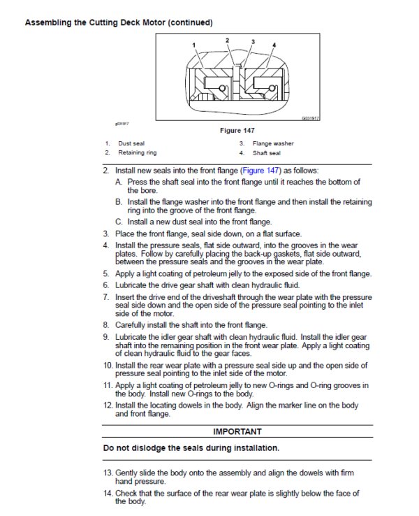
- Servicing the Cutting Deck Motor
- PTO Control Manifolds
- Servicing the PTO Control Manifold
- Filter Manifold
- Hydraulic Oil Cooler
- Cutting Deck Raise, Lower Circuit
- Front Deck Lift Cylinder
- Servicing the Front Deck Lift Cylinder
- Wing Deck Lift Cylinder
- Servicing the Wing Deck Lift Cylinder
- Lift Control Manifold
- Servicing the Lift Control Manifold
- Steering and Engine Cooling Fan Circuit
- Steering Control Valve
- Servicing the Steering Control Valve
- Steering Cylinders
- Servicing the Steering Cylinder
- Engine Cooling Fan Motor
- Servicing the Engine Cooling Fan Motor
- Steering, Engine Cooling Fan Control Manifold
- Servicing the Steering, Engine Cooling Fan Control Manifold
- DANFOSS D SERIES GEAR PUMP SEAL KIT SERVICE INSTRUCTION BULLETIN
- REXROTH VARIABLE PUMP A10VG REPAIR INSTRUCTIONS
- REXROTH VARIABLE PUMP A10VG REPAIR MANUAL
- DANFOSS H1 CLOSED CIRCUIT AXIAL PISTON PUMPS Service Repair Manual
- DANFOSS H1 CLOSED CIRCUIT AXIAL PISTON PUMPS REPAIR INSTRUCTIONS
- EATON REPAIR INFORMATION: MODEL 74318 and 74348 PISTON MOTORS
- PARKER TORQMOTORTM SERVICE PROCEDURE (TC, TB, TE, TJ, TF, TG, TH AND TL SERIES)
- EATON PARTS AND REPAIR INFORMATION: 5 SERIES STEERING CONTROL UNITS
- Chapter 5 : Electrical System
- General Information
- Toro Electronic Controllers (TEC)
- Cummins Engine Electronic Control Module (ECM)
- CAN-Bus Communications
- Electrical Drawings
- Special Tools
- Multimeter
- Dielectric Gel
- Battery Terminal Protector
- Battery Hydrometer
- Troubleshooting
- Starting Problems
- General Run and Transport Problems
- Cutting Deck (PTO) Operating Problems
- Cutting Deck Lift, Lower Problems
- InfoCenter Display
- Operator Information
- Operator Advisories
- Engine Faults
- Diagnostics
- Administration Settings
- Administration Service
- Administration About
- Electrical System Quick Checks
- Testing the Battery (Open Circuit Test)
- Testing the Charging System
- Checking the Operation of the Interlock Switches
- Testing the Component
- Key Switch
- Fuses
- Maxi Fuses
- Mega Fuses
- Cab Fuses (Groundsmaster 5910 Machine Only)
- PTO Switch
- Cutting Deck Lift Switches
- Traction Assist Switch
- Cruise Control Switch
- Throttle Control Switch
- Increment, Decrement Switch
- High-Low Speed Switch
- Headlight Switch
- Turn Signal Switch
- Windshield Wiper, Washer Switch (Groundsmaster 5910 Machine Only)
- Air Conditioning Switch (Groundsmaster 5910 Machine Only)
- Intake Air Heater Contactor
- Seat Switch
- Parking Brake Switch
- Service Brake Switches
- Main Power, Controller, Start, and Cab (Groundsmaster 5910 Machine Only) Relays
- Air Conditioning Relay (Groundsmaster 5910 Machine Only)
- Toro Electronic Controller (TEC)
- Hydraulic Valve Solenoid Coils
- Fuel Sender
- Hydraulic Fluid Temperature Sender
- Diode Assembly
- Audible Alarm
- Traction Pedal Potentiometer
- Air Filter Sensor (Machines with Serial Number Above 313000300)
- Up Limit Switches
- Adjustments
- Calibrating the Traction Pedal
- Traction Pedal Teach
- Service and Repairs
- Battery Storage
- Battery Care
- Servicing the Battery
- Hydraulic Valve Solenoid Coil
- Chapter 6 : Axles, Planetaries, and Brakes
- 1 Specifications
- Axles, Planetaries, and Brakes
- General Information
- Adjustments
- Planetary Drive Assembly Endplay (OPH-2 series planetary drives)
- Service and Repairs
- Wheels
- Brake Assembly
- Servicing the Brake
- Planetary Drive Assembly
- Servicing the OPH-2 Series Planetary Drive
- Servicing the VA02 Series Planetary Drive
- Rear Axle
- Servicing the Rear Axle
- Chapter 7 : Chassis
- General Information
- Service and Repairs
- Steering Tower
- Wing Deck Rear Impact Arm Assembly
- Lift Arm Joint Yoke
- Front Deck Lift Arms
- Wing Deck Lift Arms
- Console Arm
- Traction Pedal
- Operator Seat
- Servicing the Operator Seat
- Operator Seat Suspension (Machine with Serial Number Below 315000200)
- Operator Seat Suspension (Machine with Serial Number Above 315000200)
- Hood
- Chapter 8 : Cutting Decks
- 1 Specifications
- Cutting Decks
- General Information
- Operator’s Manual
- Castor Wheel Tire Pressure
- Blade Stopping Time
- Troubleshooting
- Factors that can Affect Quality of Cut
- Service and Repairs
- Front Cutting Deck
- Wing Cutting Deck
- Idler Assembly
- Front Deck Winglets
- Blade Spindle
- Servicing the Blade Spindle
- Castor Forks and Wheels
- Deck Skids and Rollers
- Chapter 9 : Operator Cab
- General Information
- Operator’s Manual
- Electrical Components and Schematic
- Air Conditioning System
- Cab Heater System
- Air Conditioning System Performance
- Service and Repairs
- General Precautions for Removing and Installing the Air Conditioning System Components
- Air Conditioning Compressor
- Servicing the Air Conditioning Compressor
- Roof Assembly
- Air Conditioning Condenser Assembly
- Heater and Evaporator Assembly
- ICE COMPRESSOR Service Repair Manual
- Appendix A: Foldout Drawings
- Electrical Drawing Designations
- Hydraulic Schematic (Serial Number Below 313000300)
- Hydraulic Schematic (Serial Number Above 313000300)
- Electrical Schematic Sheet 1 of 5 (Serial Number Below 313000300)
- Electrical Schematic Sheet 2 of 5 (Serial Number Below 313000300)
- Electrical Schematic Sheet 3 of 5 (Serial Number Below 313000300)
- Electrical Schematic Sheet 4 of 5 (Serial Number Below 313000300)
- Electrical Schematic Sheet 5 of 5 (Serial Number Below 313000300)
- Electrical Schematic Sheet 1 of 5 Serial Number From 313000301 to 313999999)
- Electrical Schematic Sheet 2 of 5 (Serial Number From 313000301 to 313999999)
- Electrical Schematic Sheet 3 of 5 (Serial Number From 313000301 to 313999999)
- Electrical Schematic Sheet 4 of 5 (Serial Number From 313000301 to 313999999)
- Electrical Schematic Sheet 5 of 5 (Serial Number From 313000301 to 313999999)
- Electrical Schematic Sheet 1 of 5 (Serial Number Above 314000000)
- Electrical Schematic Sheet 2 of 5 (Serial Number Above 314000000)
- Electrical Schematic Sheet 3 of 5 (Serial Number Above 314000000)
- Electrical Schematic Sheet 4 of 5 (Serial Number Above 314000000)
- Electrical Schematic Sheet 5 of 5 (Serial Number Above 314000000)
- Electrical Schematic Operator Cab (Serial Number Below 313000300)
- Electrical Schematic Operator Cab (Serial Number From 313000301 to 313999999)
- Electrical Schematic Operator Cab (Serial Number Above 314000000)
- Platform Wire Harness Drawing (Serial Number Below 310000000)
- Platform Wire Harness Diagram Sheet 1 of 2 (Serial Number Below 310000000)
- Platform Wire Harness Diagram Sheet 2 of 2 (Serial Number Below 310000000)
- Platform Wire Harness Drawing (Serial Number From 310000001 to 313000300)
- Platform Wire Harness Diagram Sheet 1 of 2 (Serial Number From 310000001 to 313000300)
- Platform Wire Harness Diagram Sheet 2 of 2 (Serial Number From 310000001 to 313000300)
- Platform Wire Harness Drawing (Serial Number From 313000301 to 313999999)
- Platform Wire Harness Diagram Sheet 1 of 2 (Serial Number From 313000301 to 313999999)
- Platform Wire Harness Diagram Sheet 2 of 2 (Serial Number From 313000301 to 313999999)
- Platform Wire Harness Drawing (Serial Number Above 314000000)
- Platform Wire Harness Diagram Sheet 1 of 2 (Serial Number Above 314000000)
- Platform Wire Harness Diagram Sheet 2 of 2 (Serial Number Above 314000000)
- Rear Wire Harness Drawing (Serial Number Below 313000300)
- Rear Wire Harness Diagram (Serial Number Below 313000300)
- Rear Wire Harness Drawing (Serial Number From 313000301 to 313999999)
- Rear Wire Harness Diagram (Serial Number From 313000301 to 313999999)
- Rear Wire Harness Drawing (Serial Number Above 314000000)
- Rear Wire Harness Diagram (Serial Number Above 314000000)
- Cab Wire Harness Drawing (Serial Number Below 314999999)
- Cab Wire Harness Diagram (Serial Number Below 314999999)
- Cab Wire Harness Drawing (Serial Number Above 315000000)
- Cab Wire Harness Diagram (Serial Number Above 315000000)
Be the first to review “Toro Groundsmaster 5900, 5910 (Models 31598, 31599) Service Repair Manual”
You must be logged in to post a review.

Reviews
There are no reviews yet.