 Service Repair Manual")
Toro Groundsmaster 4500-D, 4700-D (Model 30856, 30868) Service Repair Manual
$30.00
Manual Included:
- Service Repair Manual: 278 Pages
Specifications:
- Brand: Toro
- Model: Groundsmaster 4500-D, 4700-D (Model 30856, 30868)
- Type: Rotary Mowers
- Manuals: Service Repair Manual
- Publication Numbers: 02104SL
- Language: English
- Format: PDF
- Description
- Reviews (0)
Description
Table of Content – Groundsmaster 4500-D, 4700-D (Model 30856, 30868)
- Title Page
- Revision History
- Reader Comments
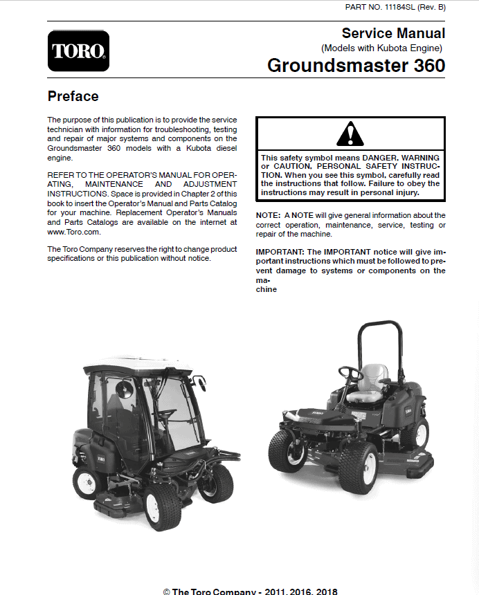
- Preface
- Table Of Contents
- 1 – Safety
- General Safety Instructions
- Before Operating
- While Operating
- Maintenance and Service
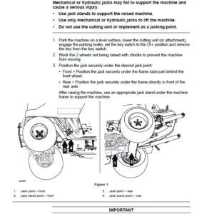
- Jacking Instructions
- Safety and Instruction Decals
- 2 – Product Records and Maintenance
- Product Records
- Equivalents and Conversions
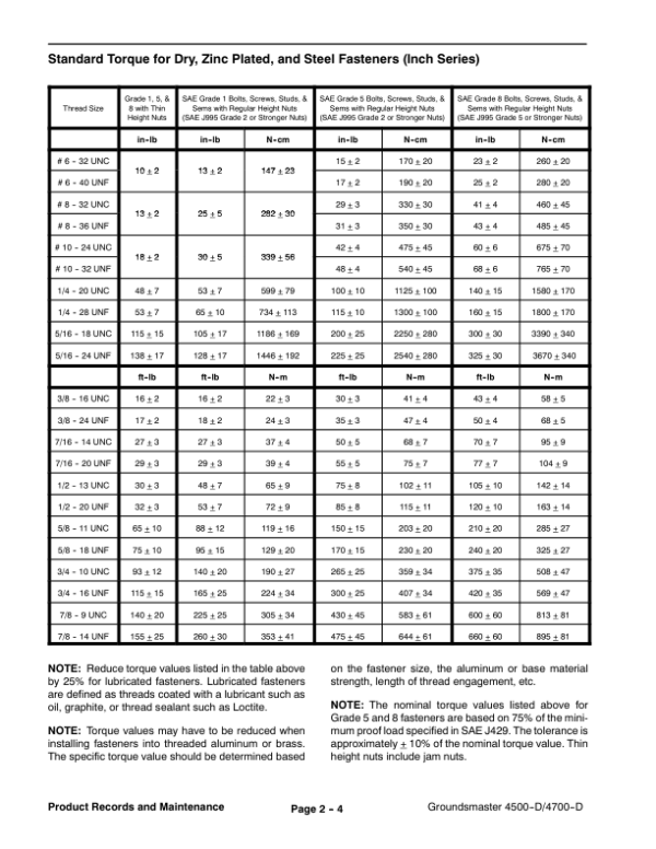
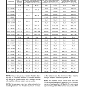
- Torque Specifications
- Maintenance
- 3 – Kubota Diesel Engine
- General Information
- Specifications
- Adjustments
- Engine Run Solenoid
- Service and Repairs
- Air Filter System
- Exhaust System
- Fuel System
- Radiator
- Engine
- Pump Adapter Plate
- Kubota V2003-T Workshop Manual
- 4 – Hydraulic System
- Specifications
- General Information
- Hydraulic Hoses
- Hydraulic Fitting Installation
- Towing Traction Unit
- Check Hydraulic Fluid
- Hydraulic Schematics
- GM 4500-D Hydraulic Schematic
- GM 4700-D Hydraulic Schematic
- Hydraulic Flow Diagrams
- Traction Circuit
- Lower Cutting Units
- Raise Cutting Units
- Mow Circuit
- Cutting Deck Blade Braking
- Steering Circuit
- Special Tools
- Troubleshooting
- Testing
- TEST NO. 1: Traction Circuit Charge Pressure
- Before Performing Hydraulic Tests
- TEST NO. 2: Traction Circuit Relief Pressure
- TEST NO. 3: Cutting Deck Circuit Pressure
- TEST NO. 4: Cutting Deck Gear Pump Flow
- TEST NO. 5: Cutting Deck Manifold Relief Pressure
- TEST NO. 6: Cutting Deck Motor Case Drain Leakage
- TEST NO. 7: Steering Circuit Relief Pressure
- TEST NO. 8: Lift, Lower Circuit Relief Pressure
- TEST NO. 9: Steering and Lift, Lower Gear Pump Flow
- TEST NO. 10: Counterbalance (RV1) Pressure
- TEST NO. 11: Rear Traction Circuit (RV5) Relief Pressure
- TEST NO. 12: Traction Circuit Reducing Valve (PR1) Pressure
- TEST NO. 13: Traction Assist (RV2) Pressure
- Service and Repairs
- General Precautions for Removing and Installing Hydraulic System Components
- Check Hydraulic Lines and Hoses
- Flush Hydraulic System
- Charge Hydraulic System
- Gear Pump
- Gear Pump Service
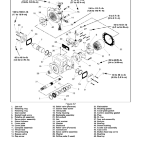
- Piston (Traction) Pump
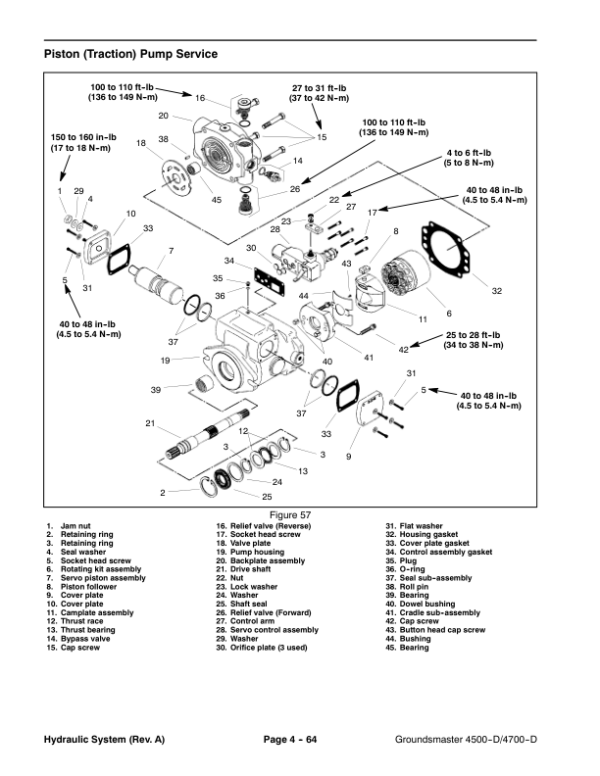
- Piston (Traction) Pump Service
- Piston Pump Manual Servo Control Assembly
- Hydraulic Control Manifolds: 2 Wheel, 4 Wheel Drive, Filtration and Charge, Power Down and Traction Assist
- Hydraulic Control Manifold Service: 2 Wheel, 4 Wheel Drive Control
- Hydraulic Control Manifold Service: Filtration and Charge Control
- Hydraulic Control Manifold Service: Power Down and Traction Assist (GM 4500–D)
- Hydraulic Control Manifold Service: Power Down and Traction Assist (GM 4700–D)
- Hydraulic Control Manifold: Deck Drive (GM 4500–D)
- Hydraulic Control Manifold Service: Deck Drive (GM 4500–D)
- Hydraulic Control Manifold: Deck Drive (GM 4700-D)
- Hydraulic Control Manifold Service: Deck Drive (GM 4700–D)
- Rear Axle Motor
- Front Wheel Motors
- Rear Axle, Front Wheel Motor Service
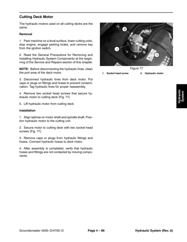
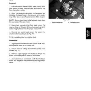
- Cutting Deck Motor
- Cutting Deck Motor Service
- Lift, Lower Control Valve (GM 4500–D)
- Lift, Lower Control Valve Service (GM 4500–D)
- Lift, Lower Control Valve (GM 4700–D)
- Lift, Lower Control Valve Service (G 4700–D)
- Steering Valve
- Steering Valve Service
- Lift Cylinders: Decks #1, #4, and #5
- Lift Cylinders: Decks #2 and #3
- Lift Cylinders: Decks #6 and #7 (GM 4700–D)
- Lift Cylinder Service
- Steering Cylinder
- Steering Cylinder Service
- Hydraulic Reservoir
- Hydraulic Oil Cooler
- 5 – Electrical System
- Electrical Schematic and Electrical Harness and Connectors Drawings
- Special Tools
- Troubleshooting
- Starting Problems
- General Run and Transport Problems
- Cutting Unit Operating Problems
- Electrical System Quick Checks
- Battery Test (Open Circuit Test)
- Check Operation of Interlock Switches
- Component Testing
- Ignition Switch
- Fuses
- Indicator Lights
- PTO and Hi–Lo Speed Control Switches
- Seat Switch
- Parking Brake Switch
- Cutting Deck Position Switch
- Cutting Deck Lift, Lower Switch
- Ramp–up Module
- Hour Meter
- Glow Relay
- Start, Neutral, Seat, Cutting Deck, Parking Brake, and High Temperature Relays
- Hydraulic Valve Solenoids
- Engine Run Solenoid
- Fuel Pump
- Glow Controller
- Temperature Sender
- Temperature Gauge
- High Temperature Shutdown Switch
- Traction Neutral Switch
- Diode Assemblies
- Diode Circuit Board
- Standard Control Module (S.N 230000001 and up)
- Service and Repairs
- Battery Storage
- Battery Care
- Battery Service
- 6 – Axles, Planetaries, and Brakes
- Specifications
- Adjustments
- Service and Repairs
- Brake Assembly
- Brake Inspection and Repair
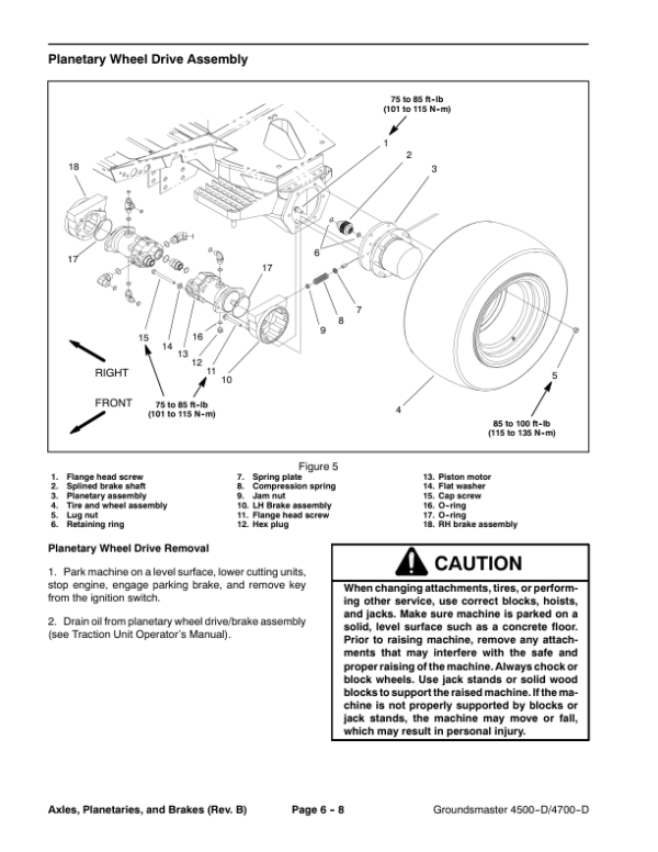
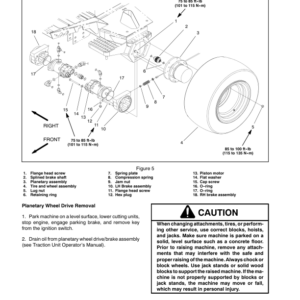
- Planetary Wheel Drive Assembly
- Planetary Wheel Drive Service
- Rear Axle Assembly
- Bevel Gear Case and Axle Case
- Differential Shafts
- Axle Shafts
- Input Shaft, Pinion Gear
- Differential Gear
- Pinion Gear to Ring Gear Engagement
- 7 – Chassis
- General Information
- Cutting Deck Identification
- Service and Repairs
- Steering Tower
- Lift Arms for Cutting Decks #1, #4, and #5
- Lift Arms for Cutting Decks #2 and #3
- Lift Arms for Cutting Decks #6 and #7 (Groundsmaster 4700–D only)
- Hood
- 8 – Cutting Units
- Specifications
- Troubleshooting
- Special Tools
- Adjustments
- Blade Stopping Time
- Blade Plane Inspection and Adjustment
- Service and Repairs
- Blade Spindle Assembly
- Blade Spindle Service
- Rear Roller
- Rear Roller Service (Non-Greasable Bearings)
- Rear Roller Service (Greasable Bearings with Retaining Ring)
- Rear Roller Service (Greasable Bearings with Bearing Nut)
- Front Roller Service
- Cutting Deck Carrier Frame
- 9 – Electrical Diagrams
- Schematic GM4500-D (S.N below 220999999)
- Schematic GM4500-D (S.N 230000001 to 260000600)
- Schematic GM4500-D (S.N 260000601 and up)
- Schematic GM4700-D (S.N below 220999999)
- Schematic GM4700-D (S.N 230000001 to 260000600)
- Schematic GM4700-D (S.N 260000601 and up)
- Glow Plug Circuit
- Crank Circuit
- Run (Transport) Circuit
- Run (Mow) Circuit
- Main Harness Diagram (S.N below 220999999)
- Main Wire Harness (S.N below 220999999)
- Main Harness Diagram (S.N 230000001 to 260000600)
- Main Wire Harness (S.N 230000001 to 260000600)
- Main Harness Diagram (S.N 260000601 and up)
- Main Wire Harness (S.N 230000601 and up)
- Console Harness Diagram (S.N below 220999999)
- Console Wire Harness (S.N below 220999999)
- Console Harness Diagram (S.N 230000001 to 260000600)
- Console Wire Harness (S.N 230000001 to 260000600)
- Console Harness Diagram (S.N 260000601 and up)
- Console Wire Harness (S.N 260000601 and up)
- Engine Harness Diagram (S.N below 220999999)
- Engine Wire Harness (S.N below 220999999)
- Engine Harness Diagram (S.N 230000001 and up)
- Engine Wire Harness (S.N 230000001 and up)
- Deck 6 and 7 Harness Diagram GM4700-D
Be the first to review “Toro Groundsmaster 4500-D, 4700-D (Model 30856, 30868) Service Repair Manual”
You must be logged in to post a review.
Reviews
There are no reviews yet.