 Service Repair Manual")
Toro Greensmaster Triflex 3300, 3400 (Models 04510, 04520) Service Repair Manual
$34.00
Manual Included:
- Service Repair Manual: 376 Pages
Specifications:
- Brand: Toro
- Model: Greensmaster Triflex 3300, 3400 (Models 04510, 04520)
- Type: Greens Reel Mowers
- Manuals: Service Repair Manual
- Publication Numbers: 12187SL
- Language: English
- Format: PDF
- Description
- Reviews (0)
Description
Table of Content – Greensmaster Triflex 3300, 3400 (Models 04510, 04520)
- Title Page
- Revision History
- Reader Comments
- Preface
- Table Of Contents
- 1 – Safety
- Table of Contents
- General Safety Instructions
- Before Operating
- While Operating
- Maintenance and Service
- Jacking Instructions
- Safety and Instruction Decals
- 2 – Product Records and Maintenance
- Table of Contents
- Product Records
- Maintenance
- Equivalents and Conversions
- Torque Specifications
- Fastener Identification
- Using a Torque Wrench with an Offset Wrench
- Standard Torque for Dry, Zinc Plated and Steel Fasteners (Inch Series)
- Standard Torque for Dry, Zinc Plated and Steel Fasteners (Metric Fasteners)
- Other Torque Specifications
- Conversion Factors
- 3 – Gasoline Engine
- Table of Contents
- Specifications
- General Information
- Operator's Manual
- Fuel Evaporative Control System
- Adjustments
- Choke Cable Adjustment
- Throttle Cable Adjustment
- Service and Repairs
- Fuel Evaporative Control System (Serial Number Below 312000000)
- Fuel Evaporative Control System (Serial Number Above 312000000)
- Fuel Tank
- Engine
- BRIGGS & STRATTON VANGUARD V−TWIN OHVREPAIR MANUAL
- 4 – Diesel Engine
- Table of Contents
- Specifications
- General Information
- Operator's Manual
- Adjustments
- Adjust Throttle Control
- Service and Repairs
- Air Cleaner Assembly
- Exhaust System
- Fuel Tank
- Radiator
- Engine
- Engine Bell Housing
- KUBOTA WORKSHOP MANUAL, DIESEL ENGINE,SM−E3B SERIES
- 5 – Hydraulic System
- Table of Contents
- Specifications
- General Information
- Operator's Manuals
- Check Hydraulic Fluid Level
- Pushing Traction Unit
- Relieving Hydraulic System Pressure
- Traction Circuit Component Failure
- Hydraulic Hoses
- Hydraulic Hose and Tube Installation (O-Ring Face Seal Fitting)
- Hydraulic Fitting Installation (SAE Straight Thread O-Ring Fitting into Component Port)
- Hydraulic Schematic
- Hydraulic Flow Diagrams
- Traction Circuit
- Lower Cutting Units
- Raise Cutting Units
- Mow and Backlap
- Right and Left Turn
- Special Tools
- Hydraulic Pressure Test Kit
- Hydraulic Tester (Pressure and Flow)
- 40 GPM Hydraulic Tester (Pressure and Flow)
- Hydraulic Hose Kit
- O-ring Kit
- High Flow Hydraulic Filter Kit
- Hydraulic Test Fitting Kit
- Measuring Container
- Wheel Hub Puller
- Troubleshooting
- Testing
- Charge Relief Valve Pressure Test (Using Tester with Flowmeter and Pressure Gauge)
- Piston (Traction) Pump Flow Test (Using Tester with Flowmeter and Pressure Gauge)
- Wheel Motor Efficiency Test (Using Tester with Flowmeter and Pressure Gauge)
- Steering, Lift Relief Valve Pressure Test (Using Pressure Gauge)
- Lower Cutting Units Relief Valve (RV) Pressure Test (Using Pressure Gauge)
- Steering, Lift Circuit Gear Pump Flow Test (Using Tester with Flowmeter and Pressure Gauge)
- Power Steering Valve Test
- Mow Circuit Gear Pump Flow Test (Using Tester with Flowmeter and Pressure Gauge)
- Mow Circuit Relief Pressure Test (Using Tester with Flowmeter and Pressure Gauge)
- Reel Motor Case Drain Flow Test (Using Tester with Flowmeter and Pressure Gauge)
- Adjustments
- Adjust Manifold Relief Valves
- Adjust Traction Control Assembly
- Service and Repairs
- General Precautions for Removing and Installing Hydraulic System Components
- Flush Hydraulic System
- Filtering Closed-Loop Traction Circuit
- Hydraulic System Start-up
- Gear Pump
- Gear Pump Service
- Piston (Traction) Pump Neutral Assembly
- Piston (Traction) Pump
- Piston (Traction) Pump Service
- Piston Pump Crush Ring Replacement
- Front Wheel Motors
- Rear Wheel Motor (Optional 3WD)
- Wheel Motor Service
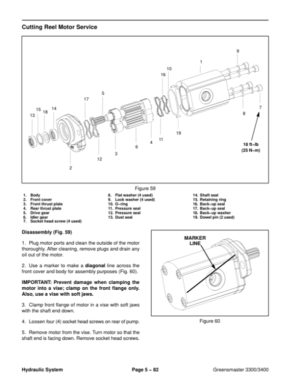
- Cutting Reel Motors
- Cutting Reel Motor Service
- Mow Control Manifold
- Mow Control Manifold Service
- Control Manifold Cartridge Valve Service
- Lift Cylinders
- Lift Cylinder Service
- Lift Control Manifold
- Lift Control Manifold Service
- Power Steering Valve
- Power Steering Valve Service
- Steering Cylinder
- Steering Cylinder Service
- Hydraulic Reservoir (Machines Equipped with Turf GuardianTM Leak Detector System)
- Hydraulic Reservoir (Machines Not Equipped with Turf GuardianTM Leak Detector System)
- Leak Detector Tank (Machines Equipped with Turf GuardianTM Leak Detector System)
- Leak Detector Solenoid Valve Assembly (Machines Equipped with Turf GuardianTM Leak Detector System)
- EATON, MEDIUM DUTY PISTON PUMP, REPAIRINFORMATION
- PARKER TORQMOTORTM SERVICE PROCEDURE
- DANFOSS STEERING UNIT TYPE OSPMService Repair Manual
- 6 – Electrical System
- Table of Contents
- General Information
- Operator's Manual
- Electrical Drawings
- Toro Electronic Controller (TEC)
- CAN-bus Communications
- Turf GuardianTM Leak Detector System Operation
- Before Start‐Up (Cold Oil)
- Normal Operation (Warm Oil)
- Leak Alert!
- Special Tools
- Multimeter
- Diagnostic Display
- Skin-Over Grease
- Battery Terminal Protector
- Dielectric Gel
- Battery Hydrometer
- Troubleshooting
- Diagnostic Light
- Diagnostic Display
- TEC Logic Chart (Greensmaster 3300)
- TEC Logic Chart (Greensmaster 3400)
- Electrical System Quick Checks
- Battery Test
- Charging System Test
- Glow Plug System Test (Greensmaster 3400)
- Adjustments
- Parking Brake Switch
- Neutral and Mow Switches
- Component Testing
- Ignition Switch (Serial Number Below 312000000)
- Ignition Switch (Serial Number Above 312000000)
- Engine Oil Pressure Indicator Light (Greensmaster 3300)
- Indicator Lights (Greensmaster 3400)
- Hour Meter
- Fuse Block (Greensmaster 3300)
- Fuse Block (Greensmaster 3400 with Serial Number Below 312000000)
- Fuse Block (Greensmaster 3400 with Serial Number Above 312000000)
- Fusible Links
- Seat Switch
- Neutral and Mow Switches
- Parking Brake Switch
- Joystick Raise and Lower Switches
- Backlap Switch
- Hydraulic Solenoid Valve Coils
- Main Power, Charge Circuit (Greensmaster 3300), Glow (Greensmaster 3400) and Fan (Greensmaster 3400) Relays
- Kill (Greensmaster 3300) and Start (Greensmaster 3400) Relays
- Toro Electronic Controller (TEC)
- CAN-bus Termination Resistors
- Turf GuardianTM Leak Detector Oil Level Sensor (If Equipped)
- Turf GuardianTM Leak Detector Alarm (If Equipped)
- Starter Solenoid (Greensmaster 3300)
- Fuel Pump (Greensmaster 3400 machines)
- Fuel Solenoid (Greensmaster 3400 machines)
- Temperature Sender (Greensmaster 3400 machines)
- Diode Assembly (Greensmaster 3400)
- Service and Repairs
- Verify Interlock System Operation
- Battery Storage
- Battery Care
- Battery Service
- 7 – Chassis
- Table of Contents
- Specifications
- General Information
- Operator's Manuals
- Special Tools
- Wheel Hub Puller
- Grease Fitting
- Adjustments
- Parking Brake Adjustment
- Service and Repairs
- Wheels
- Brake Service
- Brake Cables
- Rear Wheel Spindle Assembly
- Rear Steering Fork
- Control Console
- Tank Mount Plate Assembly
- Cutting Unit Suspension Crossarm Assembly
- Cutting Unit Suspension Assembly
- Cutting Unit Suspension Service
- Frame Assembly
- 8 – DPA Cutting Units
- Table of Contents
- Specifications
- General Information
- Cutting Unit Operator's Manual
- Supporting Cutting Unit when Servicing
- Special Tools
- Gauge Bar Assembly
- Bedknife Screw Tool
- Handle Assembly
- Roller Bearing Installation Tools
- Diameter, Circumference Measuring Tape
- Turf Evaluator Tool
- Bedknife Top Angle Indicator and Mount
- Factors That Can Affect Cutting Performance
- Set Up and Adjustments
- Characteristics
- Leveling Rear Roller
- Service and Repairs
- Backlapping
- Bedbar Assembly
- Bedknife Replacement and Grinding
- Bedbar Adjuster Service
- Reel Assembly Removal and Installation
- Reel Assembly Service
- Preparing Reel for Grinding
- Reel Motor Adapter
- Front Roller
- Rear Roller
- Roller Service
- Rear Roller Brush (Optional)
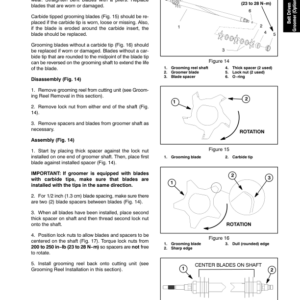
- 9 – Belt Driven Groomer (Optional)
- Table of Contents
- Specifications
- General Information
- Installation Instructions
- Troubleshooting
- Factors Affecting Grooming
- Grooming Reel Mechanical Problems
- Adjustments
- Height, Depth of Groomer Adjustment
- Service and Repairs
- Groomer Belt Replacement (Forward Rotating Groomer Drive)
- Groomer Cover (Counter Rotating Groomer Drive)
- Grooming Reel (Forward Rotating Groomer Drive)
- Grooming Reel (Counter Rotating Groomer Drive)
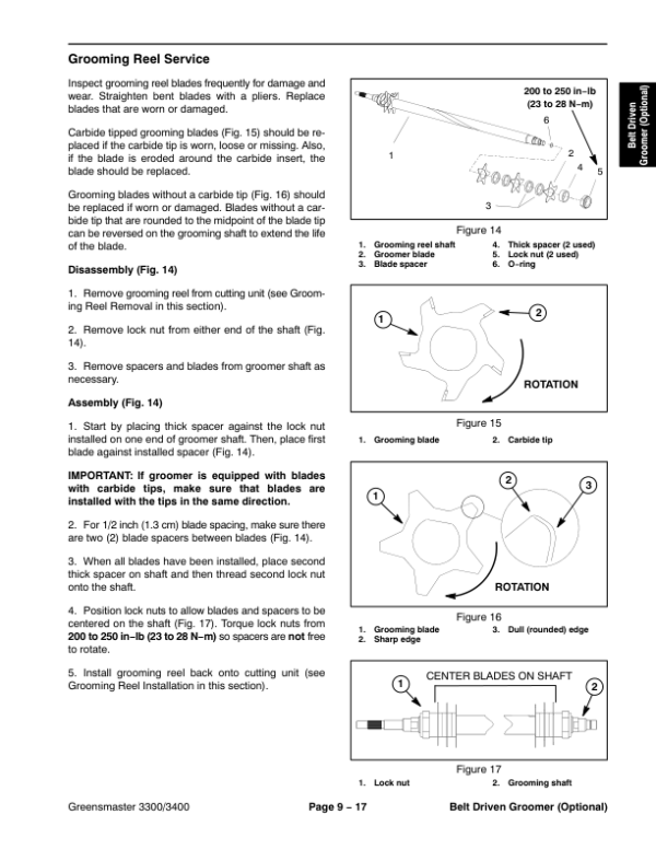
- Grooming Reel Service
- Grooming Reel Bearing Replacement
- Idler Assembly (Forward Rotating Groomer Drive)
- Idler Assembly (Counter Rotating Groomer Drive)
- Lift Arm Assembly
- Groomer Brush
- 10 : Universal Groomer (Optional)
- Specifications
- Universal Groomer
- General Information
- Installation Instructions
- Grooming Performance
- Troubleshooting
- Service and Repairs
- The Gear Box Assembly
- The Idler Assembly
- The Groomer Reel
- The Height Adjuster Assembly
- The Grooming Brush (Optional)
- 11 – Foldout Drawings
- Hydraulic Schematic
- Electrical Schematic Greensmaster 3300(Serial Number Below 312000000)
- Electrical Schematic Greensmaster 3300 (Serial Numbers 312000001 to 314000000)
- Electrical Schematic GR3400
- Greensmaster 3300 Electrical Schematic (Serial Numbers 314000001 to 316000000)
- Greensmaster 3300 Electrical Schematic (Serial Numbers 316000001 to 403410000)
- Greensmaster 3300 Electrical Schematic (Serial Numbers above 403410001)
- Electrical SchematicGreensmaster 3400(Serial Number Below 312000000)
- Electrical Schematic Greensmaster 3400(Serial Number 312000001 to 314000000)
- Greensmaster 3400 Electrical Schematic (Serial Numbers 314000001 to 316000000)
- Greensmaster 3400 Electrical Schematic (Serial Numbers 316000001 to 403420000)
- Greensmaster 3400 Electrical Schematic (Serial Numbers above 403420001)
- Wire Harness Drawing Greensmaster 3300(Serial Number Below 312000000)
- Wire Harness Drawing Greensmaster 3300 (Serial Numbers 312000001 to 316000000)
- Wire Harness Drawing Greensmaster 3300 (Serial Numbers 316000001 to 403410000)
- Wire Harness Drawing Greensmaster 3300 (Serial Numbers 403410001 to 406000000)
- Wire Harness Drawing Greensmaster 3300(Serial Numbers above 406000001)
- Wire Harness Drawing Greensmaster 3400 (Serial Number Below 312000000)
- Wire Harness Drawing Greensmaster 3400 (Serial Numbers 312000000 to 314000000)
- Wire Harness Drawing Greensmaster 3400 (Serial Numbers 314000001 to 316000000)
- Wire Harness Drawing Greensmaster 3400 (Serial Numbers 316000001 to 316000500)
- Wire Harness Drawing Greensmaster 3400 (Serial Numbers 316000501 to 403420000)
- Wire Harness Drawing Greensmaster 3400 (Serial Numbers 403420000 to 405700000)
- Wire Harness Drawing Greensmaster 3400 (Serial Numbers above 405700001)
Be the first to review “Toro Greensmaster Triflex 3300, 3400 (Models 04510, 04520) Service Repair Manual”
You must be logged in to post a review.

Reviews
There are no reviews yet.