 Service Repair Manual")
Toro Greensmaster 3150 (Model 04358) Service Repair Manual
$30.00
Manual Included:
- Service Repair Manual: 296 Pages
Specifications:
- Brand: Toro
- Model: Greensmaster 3150 (Model 04358)
- Type: Greens Reel Mowers
- Manuals: Service Repair Manual
- Publication Numbers: 12191SL
- Language: English
- Format: PDF
- Description
- Reviews (0)
Description
Table of Content – Greensmaster 3150 (Model 04358)
- Title Page
- Revision History
- Reader Comments
- Preface
- Table Of Contents
- Chapter 1 – Safety
- Safety Instructions
- Before Operating
- While Operating
- Maintenance and Service
- Jacking Instructions
- Safety and Instruction Decals
- Chapter 2 – Product Records and Maintenance
- Product Records
- Maintenance
- Equivalents and Conversions
- Torque Specifications
- Fastener Identification
- Using a Torque Wrench with an Offset Wrench
- Standard Torque for Dry, Zinc Plated and Steel Fasteners (Inch Series)
- Standard Torque for Dry, Zinc Plated and Steel Fasteners (Metric Fasteners)
- Other Torque Specifications
- Conversion Factors
- Chapter 3 – Engine
- General Information
- Operator's Manual
- Specifications
- Service and Repairs
- Fuel Tank
- Engine
- Fuel Evaporative Control System
- Briggs & Stratton Vanguard V−Twin OHV Repair Manual
- Chcpter 4 – Hydraulic System
- Specifications
- General Information
- Operator's Manual
- Check Hydraulic System Fluid
- Towing Traction Unit
- Hydraulic Hoses
- Hydraulic Hose and Tube Installation (O-Ring Face Seal Fitting)
- Hydraulic Fitting Installation (SAE Straight Thread O-Ring Fitting into Component Port)
- Hydraulic Schematic
- Hydraulic Flow Diagrams
- Traction Forward and Reverse
- Raise and Lower Cutting Units
- Mow and Backlap
- Right and Left Turn
- Special Tools
- Hydraulic Pressure Test Kit
- Hydraulic Tester (Pressure and Flow)
- O-ring Kit
- High Flow Hydraulic Filter Kit
- Hydraulic Hose Kit
- Hydraulic Test Fitting Kit
- Measuring Container
- Wheel Hub Puller
- Troubleshooting
- Refer to the Testing section of this Chapter for precautions and specific test procedures.
- General Hydraulic System Problems
- Traction Circuit Problems
- Mow Circuit Problems
- Lift, Lower Circuit Problems
- Steering Circuit Problems
- Testing
- Charge Relief Valve Pressure Test (Using Pressure Gauge)
- Wheel Motor Efficiency Test (Using Tester with Flowmeter and Pressure Gauge)
- Piston (Traction) Pump Flow Test (Using Tester with Flowmeter and Pressure Gauge)
- Gear Pump (Rear Section) Flow Test (Using Tester with Flowmeter and Pressure Gauge)
- Implement Relief Valve Pressure Test (Using Tester with Flowmeter and Pressure Gauge)
- Lower Cutting Units Relief Valve (R2) Pressure Test (Using Tester with Flowmeter and Pressure Gauge)
- Gear Pump (Front Section) Flow Test (Using Tester with Flowmeter and Pressure Gauge)
- Mow Circuit Relief Valve (S1R1) Pressure Test (Using Tester with Flowmeter and Pressure Gauge)
- Reel Motor Case Drain Flow Test (Using Tester with Flowmeter and Pressure Gauge)
- Steering Control Valve Test
- Adjustments
- Adjust Manifold Relief Valve (R2)
- Service and Repairs
- General Precautions for Removing and Installing Hydraulic System Components
- Flush Hydraulic System
- Filtering Closed-Loop Traction Circuit
- Hydraulic System Start-up
- Gear Pump
- Gear Pump Service
- Piston (Traction) Pump Neutral Assembly
- Piston (Traction) Pump
- Piston (Traction) Pump Service
- Piston Pump Crush Ring Replacement
- Front Wheel Motors
- Rear Wheel Motor (Optional 3WD)
- Wheel Motor Service
- Cutting Reel Motors
- Cutting Reel Motor Service
- Front Lift Cylinders
- Center Lift Cylinder
- Lift Cylinder Service
- Hydraulic Manifold
- Hydraulic Manifold Service
- Steering Control Valve
- Steering Control Valve Service
- Steering Cylinder
- Steering Cylinder Service
- Leak Detector
- Hydraulic Reservoir
- Eaton Model 70160 Variable Displacement Piston Pump Repair Information
- Parker Torqmotor Service Procedure TF, TG, TH and TL Series Hydraulic Torqmotors
- Danfoss Steering OSPM Service Repair Manual
- Chapter 5 – Electrical System
- General Information
- Operator's Manual
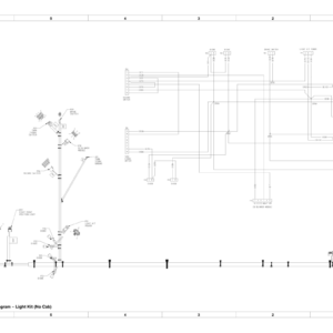
- Electrical Drawings
- Special Tools
- Multimeter
- Skin-Over Grease
- Battery Terminal Protector
- Dielectric Lubricant, Sealant
- Battery Hydrometer
- Turf Guardian™ Leak Detector System Operation
- Before Start‐Up (Cold Oil)
- Normal Operation (Warm Oil)
- Leak Alert!
- Troubleshooting
- Starting Problems
- General Run and Transport Problems
- Cutting Unit Operating Problems
- Electrical System Quick Checks
- Battery Test
- Charging System Test
- Component Testing
- Ignition Switch
- Fuse Block
- Hour Meter
- Seat Switch
- Safety Relays
- Neutral and Mow Switches
- Parking Brake Sensor
- Joystick Raise and Lower Switches
- Lower Reels Time Delay
- Starter Solenoid
- Solenoid Valve Coils
- Backlap Switch
- Diodes
- Fusible Links
- Leak Detector Test, Light Switch
- Leak Detector Alarm and Delay Timer
- Leak Detector Float Sensor
- Leak Detector Solenoid Valve
- Service and Repairs
- Battery Care
- Battery Storage
- Battery Service
- Chapter 6 – Chassis
- Specifications
- General Information
- Operator's Manual
- Special Tools
- Wheel Hub Puller
- Service and Repairs
- Front Wheel and Brakes
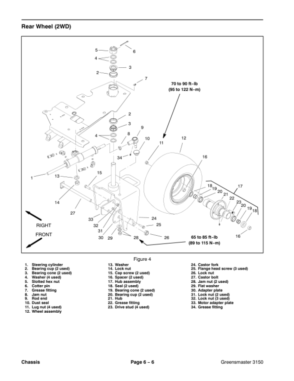
- Rear Wheel (2WD)
- Rear Wheel (Optional 3WD)
- Rear Wheel Hub and Motor Assembly (Optional 3WD)
- Rear Castor Fork
- Cutting Unit Pull Frame
- Chapter 7 – DPA Cutting Units
- Specifications
- General Information
- Cutting Unit Operator's Manual
- Supporting Cutting Unit when Servicing
- Special Tools
- Gauge Bar Assembly
- Bedknife Screw Tool
- Handle Assembly
- Roller Bearing Installation Tools
- Diameter, Circumference Measuring Tape
- Turf Evaluator Tool
- Bedknife Top Angle Indicator and Mount
- Reel Thread Repair Taps
- Factors That Can Affect Cutting Performance
- Set Up and Adjustments
- Characteristics
- Leveling Rear Roller
- Service and Repairs
- Backlapping
- Bedbar Assembly
- Bedknife Replacement and Grinding
- Bedbar Adjuster Service
- Reel Assembly
- Reel Assembly Service
- Preparing Reel for Grinding
- Front Roller
- Rear Roller
- Roller Service
- Rear Roller Brushes (Optional)
- Servicing the Rear Roller Brush (with or without a belt driven groomer)
- Servicing the Rear Roller Brush (with or without a universal groomer)
- Chapter 8 – Belt Driven Groomer (Optional)
- 1 Specifications
- General Information
- Installation Instructions
- Grooming Performance
- Troubleshooting
- Service and Repairs
- Replacing the Groomer Drive Belt
- The Groomer Plate Assemblies
- The Groomer Reel
- The Groomer Arm Assemblies
- The Grooming Brushes (Optional)
- Chapter 9 – Universal Groomer (Optional)
- 1 Specifications
- General Information
- Installation Instructions
- Troubleshooting
- Grooming Performance
- Groomer Reel Mechanical Problems
- Special Tools
- Service and Repairs
- The Gear Box Assembly
- The Idler Assembly
- The Groomer Reel
- The Height Adjuster Assembly
- The Grooming Brush (Optional)
- Appendix A: Foldout Drawings
- Electrical Drawing Designations
- Hydraulic Schematic
- Electrical Circuit Diagrams – Crank Circuits (typical)
- Electrical Circuit Diagrams – Run Circuits (typical)
- Electrical Circuit Diagrams – Raise Cutting Units Circuits (typical)
- Electrical Circuit Diagrams – Lower Cutting Units (6 seconds) Circuits (typical)
- Electrical Circuit Diagrams – Mow Circuits (typical)
- Electrical Circuit Diagrams – Backlap Circuits (typical)
- Electrical Schematic (serial numbers before 315000000)
- Electrical Schematic (serial numbers 315000000 to 403410000)
- Electrical Schematic (serial numbers above 403410000)
- Main Wire Harness Drawing (serial numbers below 315000000)
- Main Wire Harness Diagram (serial numbers below 315000000)
- Main Wire Harness Drawing (serial numbers 315000000 to 403410000)
- Main Wire Harness Diagram (serial numbers 315000000 to 403410000)
- Main Wire Harness Drawing (serial numbers above 403410000)
- Main Wire Harness Diagram (serial numbers above 403410000)
- Engine Wire Harness
Be the first to review “Toro Greensmaster 3150 (Model 04358) Service Repair Manual”
You must be logged in to post a review.

Reviews
There are no reviews yet.