Sumitomo SH210LC-5 Hydraulic Excavator Repair Service Manual
$44.00
Sumitomo Excavator SH210LC-5
Format: PDF
Manual Identification: WDL2005-2T, WLSM2105-00W, WLST2005TS-00W, WLST2105-01T, WCL2005-0F_T02
English
- Sumitomo SH210LC-5 Hydraulic Excavator Repair Service Manual – 1701 Pages
- Operators Manual – 246 Pages
- Parts Catalog – 604 Pages
- Description
- Reviews (0)
Description
Sumitomo SH210LC-5 Hydraulic Excavator Repair Service Manual
Sumitomo Excavator SH210LC-5
Format: PDF
Manual Identification: WDL2005-2T, WLSM2105-00W, WLST2005TS-00W, WLST2105-01T, WCL2005-0F_T02
English
- Sumitomo SH210LC-5 Hydraulic Excavator Repair Service Manual – 1701 Pages
- Operators Manual – 246 Pages
- Parts Catalog – 604 Pages
Sumitomo SH210LC-5 Manual TABLE OF CONTENTS
Procedures for Replacing Consumable Parts
Engine Oil …………………………………………………………………………………………………….1
Removal and Installation of Engine Oil Filter Element…………………………………………4
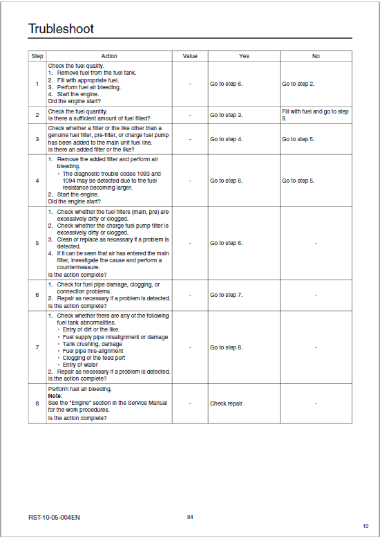
Fuel Filter……………………………………………………………………………………………………..5
Charge Fuel Pump Filter ………………………………………………………………………………..9
Removal and Installation of Fan Belt ……………………………………………………………..11
Removal and Installation of Air Conditioner Belt ………………………………………………13
Assembly and Disassembly
Removal and Installation of Engine Hood………………………………………………………..15
Removal and Installation of Engine Assembly………………………………………………….17
Removal and Installation of Starter Motor ……………………………………………………….29
Removal and Installation of Alternator…………………………………………………………….31
Removal and Installation of Supply Pump ……………………………………………………….33
Removal and Installation of Common Rail……………………………………………………….47
Removal and Installation of Injector………………………………………………………………..50
Removal and Installation of Muffler ………………………………………………………………..62
Removal and Installation of Turbo Charger ……………………………………………………..64
Removal and Installation of EGR Cooler and EGR Valve…………………………………..69
Removal and Installation of Engine Sensors ……………………………………………………73
Removal and Installation of Fuel Cooler………………………………………………………….74
Removal and Installation of Engine Inter Cooler ………………………………………………75
Air Conditioner
Assembly and Disassembly
Removal and Installation of Compressor…………………………………………………………..1
Removal and Installation of Condenser…………………………………………………………….3
Removal and Installation of Receiver Dryer ………………………………………………………5
Assembly and Disassembly of Unit ………………………………………………………………….7
Procedures for Gas Filling
Work Precautions ………………………………………………………………………………………..13
Work Procedures…………………………………………………………………………………………14
Procedures for Filling……………………………………………………………………………………16
Maintenance
Procedure for Electrical Equipment Judgment
Procedure for Electricity Measurement …………………………………………………………….1
Maintenance Standards
Check Sheet …………………………………………………………………………………………………3
Assembly and Disassembly
Track Shoe
Removal and Installation of Shoe Assembly ……………………………………………………..1
Removal and Installation of Shoe Plate…………………………………………………………….6
Travel Unit
Removal and Installation of Travel Motor…………………………………………………………..7
Assembly and Disassembly of Travel Motor …………………………………………………….15
Travel Motor Internal Structure Diagram………………………………………………………….81
Travel Motor Part Table …………………………………………………………………………………82
Take-up Roller
Removal and Installation of Take-up Roller ……………………………………………………..83
Assembly and Disassembly of Take-up Roller …………………………………………………86
Upper Roller
Removal and Installation of Upper Roller ………………………………………………………..98
Assembly and Disassembly of Upper Roller…………………………………………………..101
Lower Roller
Removal and Installation of Lower Roller ………………………………………………………112
Assembly and Disassembly of Lower Roller…………………………………………………..115
Swing Unit
SH210-5 Removal and Installation of Swing Unit ……………………………………………125
SH210-5 Assembly and Disassembly of Swing Unit ……………………………………….131
SH210-5 Assembly and Disassembly of Swing Motor……………………………………..136
SH210-5 Assembly and Disassembly of Swing Reduction Gear……………………….160
Center Joint
Removal and Installation of Center Joint ……………………………………………………….217
Counterweight
Removal and Installation of Counterweight ……………………………………………………222
Hydraulic Pump
Removal and Installation of Pump ………………………………………………………………..225
Procedures for Assembly and Disassembly of Hydraulic Pump Main Unit………….231
Pump Main Unit Maintenance Standards ………………………………………………………239
Explanation of Regulator Operation………………………………………………………………242
Procedures for Assembly and Disassembly of Regulator…………………………………248
Remote Control Valve
Removal and Installation of Operation Remote Control Valve ………………………….257
Procedures for Assembly and Disassembly of Operation Remote Control Valve…266
Removal and Installation of Travel Remote Control Valve ………………………………..279
Procedures for Assembly and Disassembly of Travel Remote Control Valve ………283
Control Valve
Removal and Installation of Control Valve ……………………………………………………..302
Procedures for Assembly and Disassembly of Control Valve ……………………………312
Other Valves
Removal and Installation of 5 Stack Solenoid ………………………………………………..335
Removal and Installation of Cushion Valve…………………………………………………….339
Assembly and Disassembly of Cushion Valve………………………………………………..343
Radiator and Oil Cooler
Removal and Installation of Radiator…………………………………………………………….351
Removal and Installation of Oil Cooler ………………………………………………………….361
Tank
Removal and Installation of Hydraulic Oil Tank……………………………………………….365
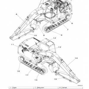
Removal and Installation of Fuel Tank…………………………………………………………..375
Attachments
Removal and Installation of Bucket……………………………………………………………….381
Removal and Installation of Bucket Link………………………………………………………..383
Removal and Installation of Bucket Cylinder ………………………………………………….386
Removal and Installation of Arm Cylinder………………………………………………………390
Removal and Installation of Arm…………………………………………………………………..395
Removal and Installation of Boom Cylinder……………………………………………………397
Removal and Installation of Boom ………………………………………………………………..402
Removal and Installation of Arm HBCV…………………………………………………………408
Removal and Installation of Boom HBCV………………………………………………………410
Procedures for Operation / Assembly and Disassembly of Hydraulic Cylinder ……413
Lights
Removal and Installation of Boom Light ………………………………………………………..442
Removal and Installation of Tool Box Light …………………………………………………….443
Procedures for Removal and Installation of Cab Inner and Outer Parts
Removal and Installation of Cab Assembly ……………………………………………………444
Removal and Installation of Operator’s Seat ………………………………………………….452
Removal and Installation of Wiper ………………………………………………………………..454
Removal and Installation of Wiper Controller …………………………………………………455
Removal and Installation of Wiper Motor……………………………………………………….458
Removal and Installation of Monitor ……………………………………………………………..462
Removal and Installation of Cab Front Glass …………………………………………………463
Procedure for Window Lock Adjustment………………………………………………………..466
Hydraulic Equipment-related Parts
Accumulator………………………………………………………………………………………………468
Suction Filter……………………………………………………………………………………………..469
Return Filter………………………………………………………………………………………………471
Pilot Filter………………………………………………………………………………………………….473
Other
Removal and Installation of Side Door ………………………………………………………….474
Draining Oil from Hydraulic Oil Tank……………………………………………………………..475
The Sumitomo Manual Preface
The purpose of this Sumitomo Excavator manual is to assist dealers and repair serviceman in efficient repair and maintenance of their machinery. Carrying out the procedures as detailed, together with the use of any special tools needed.
Using the Sumitomo SH210LC-5 Manual
To make information easier to find, there is an index at the beginning of each section listing the various parts in that section. At the beginning of each part there is a table of contents which should also be used as a guide to locate information.
To assist with locating information, each section of the manual is preceded by a contents page listing the repair operations, Each instruction within an operating has a sequence number. To complete the operation in the minimum time is possible follow the manual guideline and repair instructions.
When parts have to be replaced in either the SH210LC-5 Hydraulic Excavator , it is essential that only genuine Sumitomo parts should be used. Special attention should be paid to the following points concerning repairs and the fitting of replacement parts and accessories.
Indexing
For convenience the manual is divided into section and parts, each page bearing a section and part number. The sections are subdivided into numbered operation. This simplifies cross referencing and enable the subject to be found easily.
Be the first to review “Sumitomo SH210LC-5 Hydraulic Excavator Repair Service Manual”
You must be logged in to post a review.



Reviews
There are no reviews yet.