



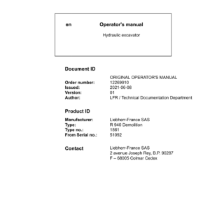


Liebherr R940 Hydraulic Excavator Operators Service Repair Manual
Price range: $24.00 through $56.00
Manual Included:
PIN/Type – 1861
- Service Repair Manual: 4460 Pages
- Operators Manual (US & Canada version): 440 Pages
- Operators Manual (Worldwide Version): 430 Pages
Specifications:
- Type: Excavator
- Model: R940
- PIN/Type: 1861
- Manuals: Operators Manual, Repair Manual
- Language: English
- Format: PDF
- Description
- Additional information
- Reviews (0)
Description
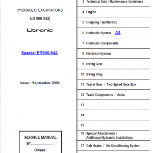
Table of Content – Liebherr R940 Hydraulic Excavator Type 1861 Manual
- Service manual
- Preface
- Contents
- 010 Introduction
- 010.010 Additions and updates in the service manual
- 010.020 Safety warnings
- 010.025 Standards and regulations
- 010.050 Special tool
- 010.060 Conservation guidelines
- 010.080 Material weights
- 020 Technical data
- 020.005 Technical data
- 030 Maintenance
- 030.005 Maintenance
- 030.057 Confirmation of maintenance
- 030.065 Adjustment checklist and procedure (from software version 156)
- 030.070 Adjustment check list and procedure (from software version 138)
- 030.071 Adjustment check list and procedure (from software version 156)
- 030.080 Adjustment check list and procedure (from software version 136)
- 030.081 Adjustment checklist and procedure (from software version 156)
- 030.085 Adjustment check list and procedure (from software version 136)
- 030.086 Adjustment check list and procedure (from software version 156)
- 030.090 Adjustment procedures and report (from software version 027)
- 040 Drive group
- 040.010 Diesel engine
- 040.020 Diesel particle filter
- 040.025 SCR system
- 040.026 Checklist modification of SCR system
- 040.040 DPVP pump distributor gear
- 050 Cooling system
- 050.010 Cooling system
- 060 Working hydraulics
- 060.001 List of hydraulic diagrams
- 060.005 Overview of hydraulic symbols
- 060.007 Colour code for lines in hydraulic schematics
- 060.010 Description of the Positive Control system
- 060.020 Depressurising a hydraulic system
- 060.028 Description of the hydraulic system
- 060.030 Components list
- 060.032 Hydraulic schematic
- 060.038 Description of the hydraulic system
- 060.040 Components list
- 060.042 Hydraulic schematic
- 060.045 Component list
- 060.046 Hydraulic schematic
- 060.048 Description of the hydraulic system
- 060.050 Components list
- 060.052 Hydraulic schematic
- 060.058 Description of the hydraulic system
- 060.060 Components list
- 060.065 Hydraulic schematic (with slewing pump)
- 060.066 Hydraulic schematic
- 060.070 Hydraulic schematic (with slewing pump)
- 060.071 Hydraulic schematic
- 060.074 Hydraulic schematic (with slewing pump)
- 060.075 Hydraulic schematic
- 060.150 Description of the hydraulic system
- 060.152 Components list
- 060.154 Hydraulic schematic
- 060.200 Description of the hydraulic system
- 060.204 Hydraulic schematic
- 060.300 Description of the hydraulic system
- 060.302 Components list
- 060.304 Hydraulic schematic – tunneling attachment
- 060.310 Safety servo control circuit
- 060.902 Component list
- 060.904 Hydraulic schematic
- 080 Hydraulic components
- 080.010 List of the hydraulic components
- 080.015 Rotary group for axial piston pumps and motors
- 080.025 Double variable-displacement pump CPVP
- 080.030 Double variable-displacement pump DPVP
- 080.050 SL-SD regulator
- 080.100 Variable-displacement pump A4 VG
- 080.150 Variable-displacement pump MVP
- 080.160 Servo control pump
- 080.170 Pump for distribution gear oil cooling
- 080.180 Gear pumps AP 212
- 080.185 Gear pumps PHP
- 080.200 Servo control unit
- 080.209 Pressure accumulator
- 080.220 Pilot control unit / joystick
- 080.230 Pilot control unit / travel pedal
- 080.240 Pilot control unit / lateral double pedal
- 080.303 Axial piston hydraulic motor MT45
- 080.304 Gear hydraulic motor APFM 212
- 080.305 FMF hydraulic motor – line B
- 080.310 CMVE travel motor
- 080.315 FMV travel motor
- 080.320 Travel brake valve (motor type FMV)
- 080.400 1-way rotary connection
- 080.402 5-way rotary connection (low pressure)
- 080.405 5-way rotary connection (high pressure)
- 080.410 6-way rotary connection
- 080.415 7-way rotary connection
- 080.500 Pressure relief valves
- 110 Electrical system
- 110.001 List of electrical diagrams
- 110.005 Overview of electrical symbols
- 110.010 Operator’s cab – arrangement of electrical components
- 110.032 Operator’s cab – electrical diagrams
- 110.080 Operator’s cab – arrangement of electrical components
- 110.081 Operator’s cab – electrical diagrams
- 110.091 Operator’s cab and uppercarriage – electrical diagrams
- 110.200 Uppercarriage – arrangement of electrical components
- 110.210 Uppercarriage – electrical diagrams
- 110.300 Uppercarriage – arrangement of electrical components
- 110.320 Uppercarriage – electrical diagrams
- 110.400 Uppercarriage – arrangement of electrical components
- 110.420 Uppercarriage – electrical diagrams
- 110.470 Uppercarriage – arrangement of electrical components
- 110.510 Uppercarriage – electrical diagrams
- 110.520 Attachment – electrical diagrams
- 110.530 Uppercarriage – main cable set
- 110.695 Diesel engine FPT – electrical diagrams
- 110.720 Diesel engine D934 – electrical diagrams
- 110.740 Diesel engine D936 – electrical diagrams
- 110.750 Diesel engine D944 – electrical diagrams
- 120 Travel gearbox
- 120.005 List of travel gearbox
- 120.010 Travel gearbox – line P(c)
- 120.015 Travel gearbox – line P(r)
- 120.020 Travel brakes
- 120.200 Adjusting the secondary pressure-relief valves for travel gear movements (motor type CMVE)
- 120.210 Adjusting the secondary pressure-relief valves for travel gear movements (motor type FMV)
- 130 Travel gear
- 130.100 Arrangement of track components
- 130.410 Wear limits for the track components
- 130.500 Track complete
- 130.530 Repair of a track
- 130.600 Tension unit complete
- 130.630 Idler-wheel
- 130.650 Grease tensioner
- 130.700 Monoblock tensioner
- 130.750 Preassembled spring tensioner
- 130.800 Track roller
- 130.850 Carrier roller supported on one side
- 130.860 Carrier roller supported on both sides
- 130.900 Face seals
- 140 Steel parts of the basic machine
- 140.010 Repair welding guideline
- 140.100 Counterweight
- 150 Working attachment
- 150.010 Hydraulic cylinders
- 150.050 Adjustment of the movements of the working attachment
- 150.090 Stick and hoist cylinder shut-down
- 150.095 Stick cylinder protection (damping)
- 150.100 Regeneration and line break safety valve for hoist cylinder
- 150.112 Line break safety valve for adjustable boom cylinder
- 150.115 Regeneration and line break safety valve for stick cylinder
- 150.120 Regeneration and line break safety valve of stick cylinder
- 150.125 Line break safety valve for stick cylinder
- 150.150 Calibrating control of line break safety valves (LBS valves)
- 150.220 Load-holding valve for bucket cylinder
- 150.230 Power supply of bucket cylinder or grapple cylinder
- 150.300 Calibration of the LDC angle transmitters
- 150.350 Preparation for third party hydraulic quick coupler
- 150.400 Removing and installing the stick to the boom
- 150.800 Dozer blade
- 150.820 Support blade
- 160 Cab, heating and air conditioning
- 160.055 Air conditioning unit: design and function
- 160.060 Air conditioning unit: malfunctions
- 160.065 Air conditioning unit: maintenance
- 160.070 Air conditioning unit: repair
- 160.100 Hydraulically adjustable cab
- 160.105 Auxiliary heater
- 170 Lubrication system
- 170.012 Central lubrication system
- 170.020 Troubleshooting
- 170.030 Lubricating pump
- 170.040 Progressive distributor SXE-2
- 170.050 Progressive distributor MX-F
- 170.060 Installing and repairing lubrication hoses
- 180 Slewing gearbox and slewing ring
- 180.010 Slewing gear mechanism SAT
- 180.050 Slewing ring
- 180.070 Slewing ring: changing the grease
- 180.080 Slewing ring: draining water
- 190 Equipment and options
- 190.015 High pressure circuit 1
- 190.025 Big rotary cutter
- 190.035 High pressure circuit 2
- 190.055 Small flow circuit
- 190.060 Medium pressure circuit (AS2)
- 190.075 Tiltrotator
- 190.079 Hydraulically adjustable cab
- 190.085 Increasing the traction
- 190.100 Stick and hoist cylinder shut-down
- 190.112 Hoist cylinder protection
- 190.115 Stick cylinder protection (damping)
- 190.118 Floating position of hoist cylinders
- 190.120 Hydraulic quick change system
- 190.122 Preparation for third party hydraulic quick coupler
- 190.125 Likufix hydraulic coupling system
- 190.127 Tool Management
- 190.130 Line break safety valve for attachment cylinders
- 190.140 Undercarriage with hydraulically variable gauge
- 190.145 Hydraulically removable counterweight
- 190.150 Generator
- 190.155 Watering device
- 190.160 Bypass filter
- 190.165 Hydraulic hammer return filter
- 190.170 Changing over the control
- 190.172 Bypass to open the shear
- 190.175 Slewing gear brake (pedal)
- 190.178 Flow distributor
- 190.185 Adjustable boom
- 190.190 LiDAT remote diagnosis system (LiTU 2 – Master 4)
- 190.191 LiDAT remote diagnosis system (LiTU 3 – Master 5)
- 190.195 Radio
- 190.200 Headlights and beacon
- 190.305 Electric refuelling pump
- 190.320 Pre-heating
- 190.323 Activating the airflow reversal for cleaning the cooler
- 190.340 Auxiliary heater
- 190.400 Travel alarm
- 190.410 Screen wiper
- 190.415 Overload warning system
- 190.440 Video surveillance
- 190.450 Skyview 360°
- 200 Diagnosis
- 200.005 Updating the machine software (Master 4)
- 200.008 Update of the machine software (Master 5)
- 200.010 Connect SCULi diagnostic software (Master 5)
- 200.015 LiFT function (Master 5)
- 200.020 Service file (Master 5)
- 200.025 Reset Master (Master 5)
- 200.030 Machine software backup (Master 5)
- 200.050 Recording error messages of master module
- 200.070 Incompatibilities of the options
- 200.200 CAN data transmission
- 200.260 CAN input and output modules
- 200.270 Addressing of CAN modules
- 200.400 Addressing of side area camera
- 200.405 Troubleshooting for camera
- 200.410 Display
- 200.420 Standalone display
- 200.425 Demolition display
- 200.505 Connection to Sculi
- 200.530 Sculi – access to the variables
- 200.600 Sculi – Wizard utility
- 200.610 Sculi – Wizard utility, additional menus for demolition machines
Additional information
| PIN Type | Type 1861 |
|---|---|
| Manual | Service Repair Manual, Operators Manual (US & Canada version), Operators Manual (Worldwide Version) |
Be the first to review “Liebherr R940 Hydraulic Excavator Operators Service Repair Manual”
You must be logged in to post a review.
Reviews
There are no reviews yet.