

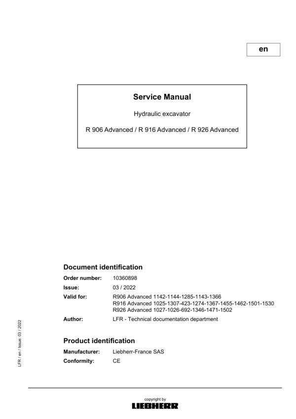
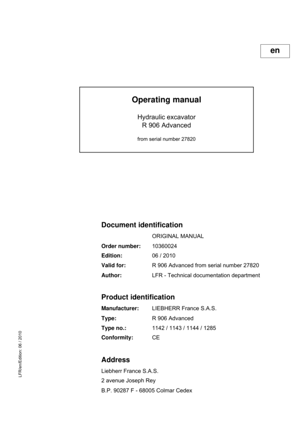
Liebherr R906 Advanced Hydraulic Excavator Operators Service Repair Manual
Price range: $22.00 through $40.00
Manual Included:
PIN/Type – 1142, 1143, 1144, 1285, 1366
- Service Repair Manual: 1002 Pages
- Operating Manual (SN between 27820: 31143)- 391 Pages
- Operating Manual (SN between 18002: 27819) – 369 Pages
- Operating Manual (SN after 31144 ): 352 Pages
Specifications:
- Type: Excavator
- Model: R906 Advanced
- PIN/Type: 1142, 1143, 1144, 1285, 1366
- Manuals: Repair Manual
- Language: English
- Format: PDF
- Description
- Additional information
- Reviews (0)
Description
Table of Content – Liebherr R906 Advanced Hydraulic Excavator Type 1142, 1143, 1144, 1285, 1366 Manual
- Front page
- Contents
- Introduction
- 1 General information
- 1.10: Safety instructions
- 1.20: Standards and regulations
- 1.50: Lubricants and operating fluids
- 1.60: Conservation guidelines
- 2 Tools
- 2.01: Special tools for maintenance and repair
- 2.02: Special tools for Liebherr Diesel engines D 934 / D 936
- 2.03: Special tool for the hydraulic system
- 2.04: Service Case Advanced
- 2.06: Special tools for electrical connectors
- 2.08: Common tools
- 2.12: Mounting tools for hydraulic cylinders
- 2.14: Wrench for the slotted nut on the swing gear SAT
- 2.15: Compression device for brake piston of gear SAT
- 2.19: Tools for installing the slipring seals
- 2.25: Tools for the dismantling of the hoist cylinder bolts
- 3 Technical data / Maintenance guidelines
- 3.10: Technical data
- 3.12: Technical data
- 3.13: Technical data
- 3.40: Confirming the service
- 3.50: Control and maintenance chart
- 3.70: Lubrication chart
- 4 Engine / Motor
- 4.10: Technical data for LIEBHERR Engine Type: D 934 S A6
- 4.26: Installation and check list for Diesel particle filter
- 4.27: Liebherr Diesel particle filter (accessory kit)
- 4.40: Datalogger
- 5 Coupling / Splitterbox
- 5.10: Coupling
- 5.30: Pump distribution gear – construction line DPVP
- 6 Hydraulic system
- 6.02: Adjustment check list and adjustment guidelines
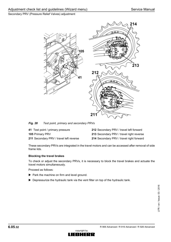
- 6.05: Adjustment check list and guidelines (Wizard menu)
- 6.10: Adjustment protocol and guidelines (menu wizard, from device software version V137)
- 6.68: Description of the Positive Control system
- 6.69: Description of the hydraulic system
- 6.80: Hydraulic Schematics – Components List
- 6.90: List of hydraulic schematics – Standard executions
- 7 Hydraulic components
- 7.01: Hydraulic pump: Removal, installation, Start-up.
- 7.11: Variable-displacement twin pump DPVP
- 7.20: Hydraulic motors schedule
- 7.21: FMF hydraulic fixed displacement motor
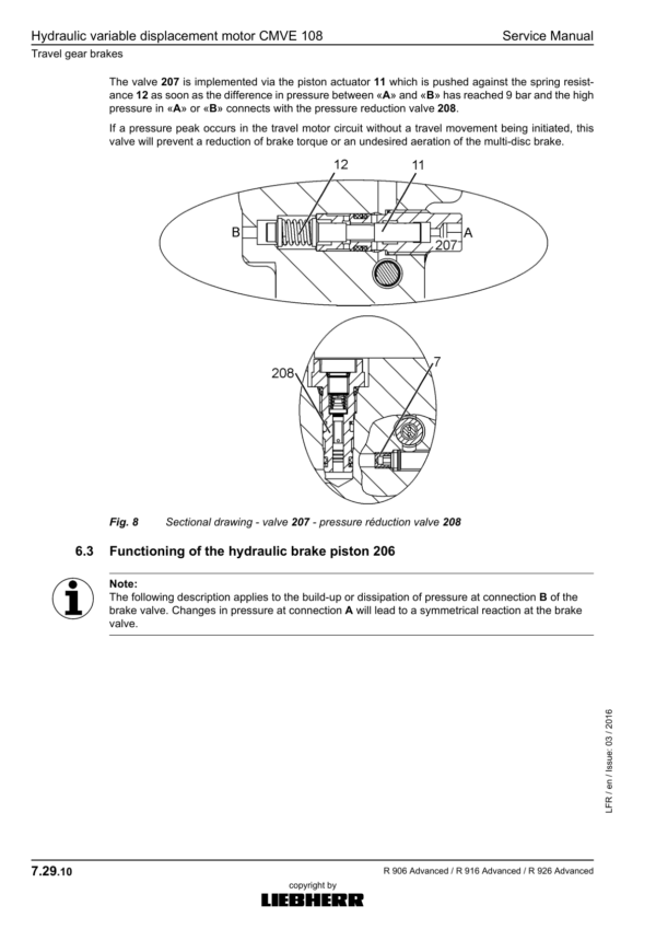
- 7.29: Hydraulic variable displacement motor CMVE 108
- 7.30: Hydraulic cylinders
- 7.31: Presentation of the cylinders of the attachments
- 7.32: Installations for pistons and piston nuts by hydraulic cylinders
- 7.33: List of the hydraulic cylinders (R 906 Advanced)
- 7.45: Regulating and servo oil unit
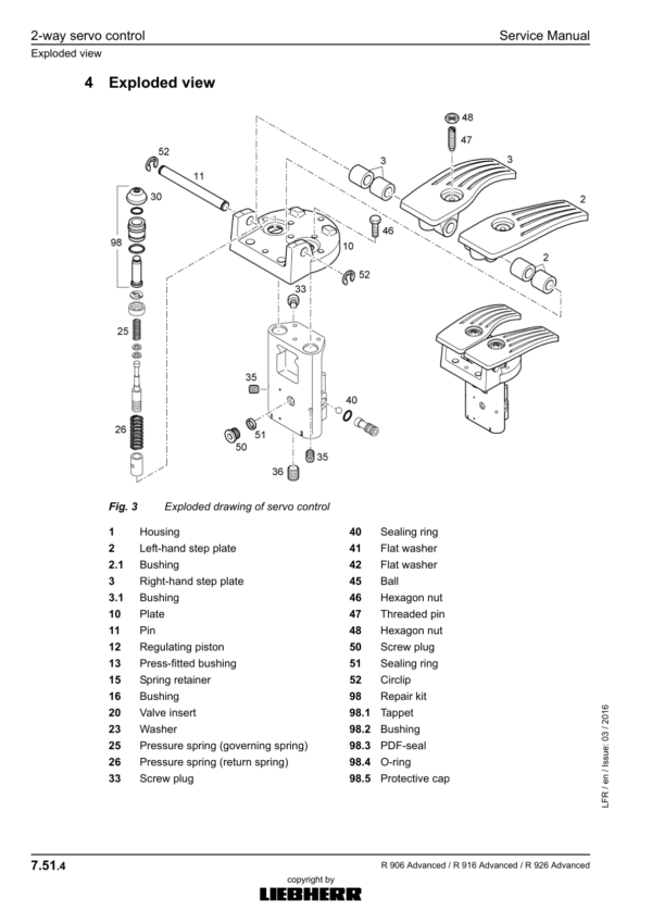
- 7.51: 2-way servo control
- 7.55: 4-way servo control (working functions)
- 7.56: Hydraulic pilot control device with 2 pedals and damping system
- 7.75: 1-way rotary connection
- 7.78: 6-way rotary connection
- 7.79: 7-way rotary connection
- 7.84: Shockless Pressure Relief Valve
- 8 Electrical system
- 8.10: Operator’s cab – arrangement of electrical components
- 8.15: Basic machine – arrangement of electrical components
- 8.70: CAN data transmission
- 8.72: CAN input and output modules
- 8.73: Addressing of CAN modules
- 8.74: Display menus
- 8.75: Connection to Sculi
- 8.76: Sculi – access to the system parameters
- 8.78: Sculi – Wizard utility
- 8.80: Software change
- 8.90: List of electrical diagrams – Standard execution
- 10830558_Uppercarriage
- 9 Swing gear
- 9.10: Swing gear «SAT»
- 9.20: Swing brake / Positioning brake
- 10 Swing ring
- 10.10: Swing ring
- 11 Travel gear
- 11.10: Gear types schedule
- 11.15: Technical data of the travel gears
- 11.35: Travel gear FAT of construction line P(c)
- 11.40: Removing and reinstalling the travel gears FAT
- 11.45: Installation and dismantling of the travel gear motor
- 11.75: Slipring seals
- 12 Track components
- 12.10: Track components of crawler excavators
- 12.22: List of the track components on R 906 Advanced
- 12.30: Wear on the track components
- 12.32: Wear limits for chains
- 12.35: Wear limits for rollers
- 12.38: Wear limits for guide & sprocket wheels
- 12.40: Removal, installation of track components
- 12.51: Spring tension units – technical data
- 12.55: Spring tension unit preassembled
- 12.58: Tension unit and guide wheel unit
- 12.70: Track roller
- 12.75: Carrier roller (supported on one side)
- 12.80: Slipring seals
- 16 Options
- 16.20: Additional attachment AHS 11 with Tool Control
- 16.24: Additional attachment AHS 12 with Tool Control
- 16.28: Rotating device (AS2)
- 16.30: Refuelling pump
- 16.40: Overload warning system
- 16.48: Stick and hoist cylinder shut-down
- 16.91: List of diagrams
- 17 Cab / Heater / Air conditioning system
- 17.30: Auxiliary heating D5WS
- 17.48: Air-conditioning system
- 17.49: Air-conditioning system service
- 18 Central lubrication
- 18.05: Central lubrication system
- 18.30: Troubleshooting
- 18.51: Lubrication pump
- 18.61: Progressive distributor SX-E
- 18.66: Progressive distributor MX-F
- 18.81: Lube hoses repair instructions
Additional information
| PIN Type | Type 1142 & 1143 & 1144 & 1285 & 1366 |
|---|---|
| Manual | Service Repair Manual, Operators Manual (SN between 27820, Operators Manual (SN between 18002 – 27819), Operators Manual (SN after 31144 ) |
Be the first to review “Liebherr R906 Advanced Hydraulic Excavator Operators Service Repair Manual”
You must be logged in to post a review.

Reviews
There are no reviews yet.