
Liebherr R900 C Litronic Hydraulic Excavator Operators Service Repair Manual
Price range: $20.00 through $36.00
Manual Included:
PIN/Type – 971, 981, 982
- Service Repair Manual: 873 Pages
- Operators Manual: 230 Pages
Specifications:
- Type: Excavator
- Model: R900 C Litronic
- PIN/Type: 971, 981, 982
- Manuals: Operators Manual, Repair Manual
- Language: English
- Format: PDF
- Description
- Additional information
- Reviews (0)
Description
Table of Content – Liebherr R900 C Litronic Hydraulic Excavator Type 971, 981, 982 Manual
- Index
- Group 1: General Information
- 1.10: Safety instructions
- 1.20: Tightening torques
- 1.22: Assembly instruction for pistons and piston nuts (hydraulic cylinders)
- 1.24: Assembly instruction for piston rod bearings with external threads (hydraulic cylinders)
- 1.25: Tightening torques of screws with LH-washer 340HV
- 1.26: Preloads and tightening torques (Din 13)
- 1.50: Fuel and Lubricants
- Group 2: Tools
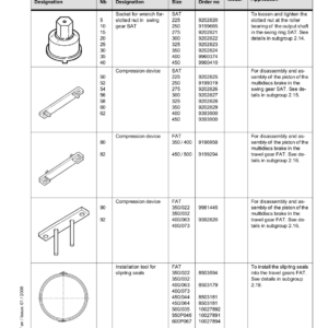
- 2.01: Special tools for maintenance and repair
- 2.02: Special tools for Liebherr Diesel engines
- 2.03: Special tools for the hydraulic system
- 2.06: Special tools for electrical connectors
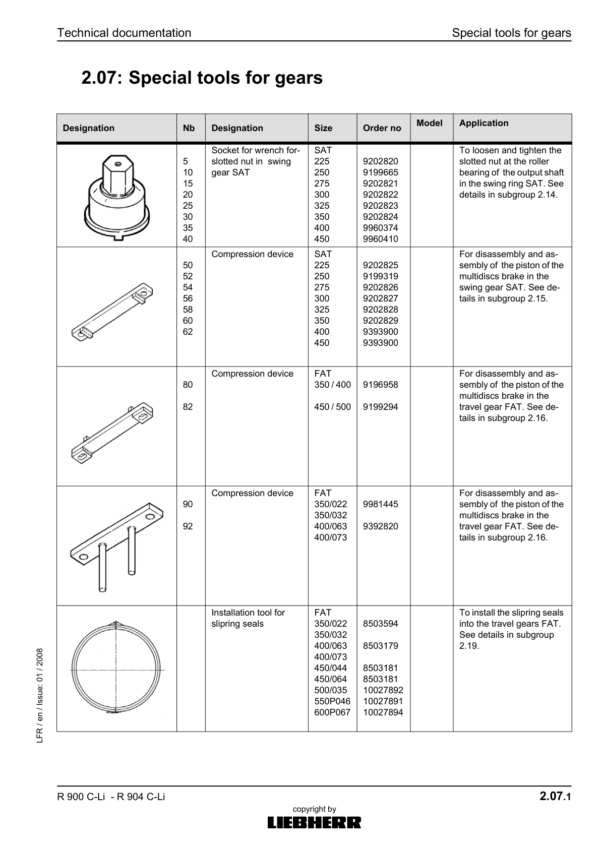
- 2.07: Special tools for gears
- 2.08: Common tools
- 2.10: Measuring tool for spool travel
- 2.12: Mounting tools for hydraulic cylinders
- 2.14: Wrench for the slotted nut on the swing gear SAT
- 2.15: Compression device for brake piston of gear SAT
- 2.16: Compression device for brake piston of gear FAT
- 2.17: Mounting device for disk brake on travel gear
- 2.19: Eichwerten LMS System / Valeurs de calibrage
- 2.21: Pump test kit
- 2.22: Tools for installing the slipring seals
- Group 3: Technical Data / Maintenance guidelines
- 3.51: Technical data
- 3.52: Technical data
- 3.64: Maintenance and Inspection Chart
- 3.65: Maintenance and Inspection Chart
- 3.71: Lubrication Chart R900C
- Group 4: Diesel Engines
- 4.11: Technical Data Diesel Engines
- Group 5: Coupling / Splitterbox
- 5.10: Coupling
- Group 6: Hydraulic system
- 6.61: Adjustment Check List R 900 C Litronic (10.11.05)
- 6.68: LSC-System
- 6.69: Layout of Hydraulic System
- 6.70: Setting instructions for the hydraulic system
- 6.81: Hydraulic system – R 900 C
- 6.82: Hydraulic system
- Group 7: Hydraulic Components
- 7.01: Installation and dismantling / start-up of hydraulic pumps
- 7.04: Variable Displacement Pump LPV
- 7.05: Variable displacement pump DPVO
- 7.22: Hydraulic fixed displacement motor FMF
- 7.28: Hydraulic variabe displacement motor FMV
- 7.30: Hydraulic cylinders
- 7.31: Extension and retraction speeds
- 7.34: Hydraulic Cylinders – R 900 C
- 7.36: Tightening values for pistons and piston nuts WN 4121
- 7.42: Control Oil and Control Unit
- 7.50: 1-way servo control
- 7.51: 2-way servo control
- 7.52: 2-way servo control
- 7.53: 2-way servo control
- 7.54: 4-way servo control
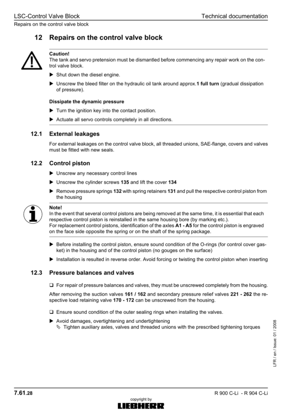
- 7.61: LSC-Control Valve Block
- 7.64: Inspecting the control valve blocks for leak oil
- 7.75: 1-way rotary connection
- 7.77: 5-way rotary connection
- 7.79: 7-way rotary connection
- 7.80: TC-valve
- 7.90: Throttle check valve for bucket cylinder
- 7.98: Brake valve for hydraulic travel gear motor
- Group 8: Electrical System
- 8.55: Arrangement of Components
- 8.70: Excavator Control BST
- 8.72: Monitoring Display Upwards of V5.5
- 8.74: Control unit S2
- 8.80: Summary of error codes
- 8.81: Electrical system
- Group 9: Swing Gear Transmission
- 9.10: Swing gear “SAT“
- 9.20: Swing gear brake
- Group 10: Swing Ring
- 10.10: Ball swing ring
- Group 11: Travel Gear
- 11.51: Travel gear transmission
- 11.71: Travel gear brake
- 11.75: Slide ring seal
- Group 12: Track components
- 12.50: Travel gear
- 12.56: Wear of track components
- 12.60: Wear limits B60/B60L and D6C
- 12.61: Wear limits D7 & B6HD – B6
- 12.62: Dismantling and installing track components
- 12.76: Installing and dismantling idler «Berco»
- 12.81: Tensioning unit
- 12.91: Track roller
- 12.96: Carrier roller
- Group 16: Options
- 16.02: Load holding valves for Hoist Cylinders
- 16.11: AHS 11 hydraulic installation kit
- 16.16: AHS 12 hydraulic installation kit
- 16.21: AHS 11 hydraulic installation kit with Tool Control
- 16.26: AHS 12 hydraulic installation kit with Tool Control
- 16.31: Schemas / Circuit Diagrams / Schémas
- 16.32: Schemas / Schemes / Schémas
- 16.51: Hydraulic schematics for options
- 16.52: Electric schematics for options
- Group 17: Cab / Heater / Air-Conditioning System
- 17.30: Auxiliary heating
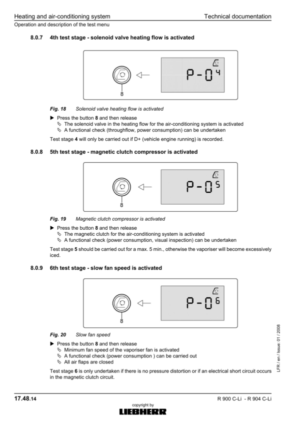
- 17.48: Heating and air-conditioning system
- Group 18 : Centralized lubrication
- 18.50: Lube hoses repair instructions
- 18.51: Centralized lubrication system
- 18.56: Pump of the centralized lubrication system
- 18.58: Progressive distributor SX-E
- 18.59: Progressive distributor MX-F
Additional information
| PIN Type | Type 971 & 981 & 982 |
|---|---|
| Manual | Service Repair Manual, Operators Manual |
Be the first to review “Liebherr R900 C Litronic Hydraulic Excavator Operators Service Repair Manual”
You must be logged in to post a review.
Reviews
There are no reviews yet.