
Liebherr R308 Hydraulic Excavator Operators Service Repair Manual
$40.00
Manual Included:
- Service Repair Manual: 2010 pages
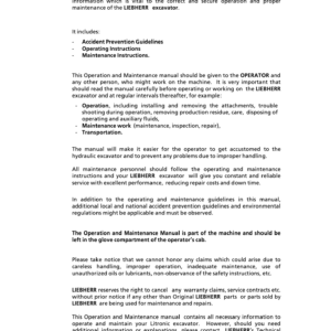
- Operators Manual: 139 pages
Specifications:
- Type: Excavator
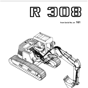
- Model: R308
- PIN/Type: All
- Manuals: Operators Manual, Repair Manual
- Publication Numbers: 8718265, 8717522
- Language: English
- Format: PDF
- Description
- Reviews (0)
Description
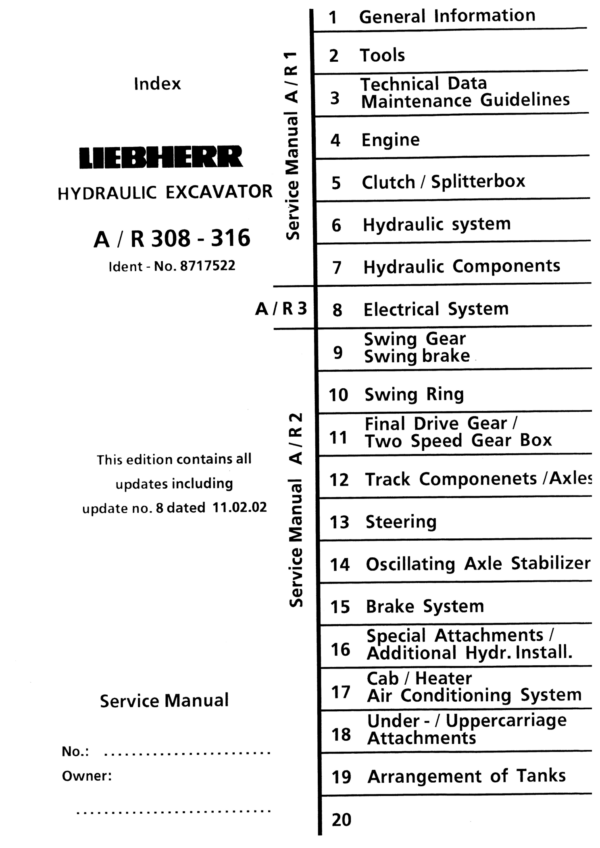
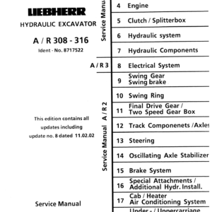
Table of Content – Service Repair Manual (R 308)
– Book I group 1- 7 (Page -1)
– Index (Page 1)
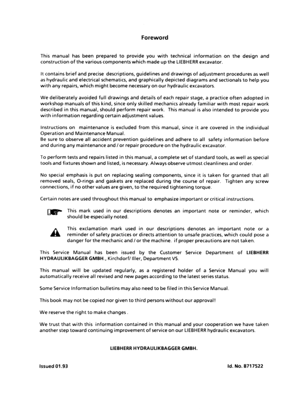
– Foreword (Page 3)
– Page index 1-7 (Page 5)
– Book II Group 8 (Page 17)
– Index (Page 17)
– Page Index 8 (Page 19)
– Book III group 9-19 (Page 27)
– Index (Page 27)
– Page Index 9-19 (Page 29)
– 1. General Information (Page 43)
– 1.10 Safety Guidelines (Page 45)
– 1.20 Charts / Norms (Page 55)
– 1.50 Service Fluids (Page 69)
– 1.55 Oil Specification Chart “LS-Oil” (Page 79)
– Tools (Page 85)
– 2.01 Listing of special tools for excavators (general) (Page 87)
– 2.03 Listing of special tools for Deutz Engine (Page 99)
– 2.05 Listing of special tools for hydraulic system (Page 119)
– 2.06 Listing of special tools for electrical connectors (Page 135)
– 2.07 Listing of special tools for gears (Page 145)
– 2.08 Listing of special tools for axles (Page 151)
– 2.10 Listing of special tools for Piston Wrech (Page 161)
– 2.11 Listing of special tools for Special assy spanner (Page 163)
– 2.12 Listing of special tools for Removal device (Page 165)
– 2.13 Listing of special tools for Ring nut spanner (Page 171)
– 2.14 Listing of special tools for Spool travel measuring tool (Page 173)
– 2.15 Listing of special tools for Testing device (Page 175)
– 2.16 Listing of special tools for Push out and centering pin (Page 177)
– 2.17 Listing of special tools for Intermiate plate (Page 179)
– 3. Technical Data / Maintenance Guidelines (Page 181)
– 3.08 Technical Data A 308 from 101 (Page 183)
– 3.09 Technical Data R 308 from 101 (Page 185)
– 3.10 Technical Data A 310 from 101 (Page 187)
– 3.11 Technical Data A 310 B from 1001 (Page 189)
– 3.12 Technical Data R 310 from 101 (Page 191)
– 3.13 Technical Data R 310 B from 1001 (Page 193)
– 3.14 Technical Data A 312 from 101 (Page 195)
– 3.16 Technical Data R 312 from 101 (Page 199)
– 3.17 Technical Data A 316 from 101 (Page 201)
– 3.18 Maintenance Guidelines A 308 from 101 (Page 205)
– 3.19 Maintenance Guidelines R 308 from 101 (Page 207)
– 3.20 Maintenance Guidelines A 310 from 101 (Page 209)
– 3.21 Maintenance Guidelines A 310 B from 1001 (Page 211)
– 3.22 Maintenance Guidelines R 310 from 101 (Page 213)
– 3.23 Maintenance Guidelines R 310 B from 1001 (Page 215)
– 3.24 Maintenance Guidelines A 312 from 101 (Page 217)
– 3.26 Maintenance Guidelines R 312 from 101 (Page 219)
– 3.28 Maintenance Guidelines A 316 from 101 (Page 221)
– 4. Engine (Page 223)
– 4.08 Engine BF 4 M 1011 F A/R 308 from 101 (Page 225)
– 4.09 Engine BF 4 M 2011 A 308 from 12009 / R 308 from 12069 (Page 229)
– 4.10 Engine BF 4 L 1011 A/R 310 from 101 (Page 233)
– 4.12 Engine BF 4 M 1012 E A/R 310 B from 1001 / A/R 312 from 101 (Page 237)
– 4.14 Engine BF 4 M 1013 E A 316 from 101 (Page 241)
– 5. Clutch / Splitterbox (Page 245)
– 5.05 Elastic Coupling A/R 308 / A/R 310 / A/R 312 from 101 / A/R 310 B 1001 (Page 247)
– 5.10 Elastic Coupling A 312 from 861 / R 312 from 257 / A 316 from 101 (Page 251)
– 6. Hydraulic system (Page 255)
– 6.08 Hydraulic System Pressure Settings and Flow A 308 from 101 (Page 257)
– 6.09 Hydraulic System Pressure Settings and Flow R 308 from 101 (Page 259)
– 6.10 Hydraulic System Pressure Settings and Flow A 310 from 101 / A 310 B from 1001 (Page 261)
– 6.11 Hydraulic System Pressure Settings and Flow R 310 from 101 / R 310 B from 1001 (Page 265)
– 6.12.01 Hydraulic System Pressure Settings and Flow A 312 from 101 (Page 269)
– 6.12.05 Hydraulic System Pressure Settings and Flow R 312 from 101 (Page 271)
– 6.13 Hydraulic System Pressure Settings and Flow A 316 from 101 (Page 273)
– 6.14 Adjustment Procedure A/R 308 from 101 (Page 275)
– 6.15 Adjustment Procedure A/R 310 from 101 (Page 279)
– 6.16 Adjustment Procedure A/R 310 B from 1001 (Page 283)
– 6.17 Adjustment Procedure A/R 312 from 101 (Page 287)
– 6.18 Adjustment Procedure A 312 from 861 (Page 291)
– 6.19 Adjustment Procedure A 316 from 101 (Page 295)
– 6.20 Hydraulic System – High and Low Pressure Circuit A 308 from 101 / A 310 B from 1001 (Page 299)
– 6.25 Hydraulic System – High and Low Pressure Circuit R 308 from 101 / R 310 B from 1001 (Page 307)
– 6.30 Hydraulic System – High Pressure Circuit A 310 from 101 (Page 315)
– 6.35 Hydraulic System – Low Pressure Circuit A 310 from 101 (Page 319)
– 6.40 Hydraulic System – High Pressure Circuit R 310 from 101 (Page 323)
– 6.45 Hydraulic System – Low Pressure Circuit R 310 from 101 (Page 327)
– 6.60 Hydraulic System A 312 from 101 (Page 331)
– 6.61 Hydraulic System A 312 from 861 (Page 335)
– 6.65 Hydraulic System R 312 from 101 (Page 339)
– 6.66 Hydraulic System R 312 from 257 (Page 343)
– 6.80 Hydraulic System A 316 from 101 (Page 347)
– 6.81 Hydraulic System A 316 from 206 (Page 351)
– 7. Hydraulic Components (Page 355)
– 7.10 Variable Displacement Pumps A 10 V “DFLR/DFLR” R 310 from 101 (Page 357)
– 7.12 Variable Displacement Pumps A 10 V “DFSR/DSLR” A 310 from 101 (Page 369)
– 7.14 Variable Displacement Pumps A 10 V “DFSR/DFSR” A/R 308 from 101 / A/R 310 B from 1001 / A/R 312 from 101 (Page 385)
– 7.15 Variable Displacement Pumps A 11 V “LRDC” A 312 from 861 / R 312 from 257 / A 316 from 101 (Page 401)
– 7.16 Pump Flow Diaqgramm A/R 308 from 101 (Page 415)
– 7.17 Pump Flow Diaqgramm A/R 310 from 101 (Page 417)
– 7.18 Pump Flow Diaqgramm A/R 312 from 101 (Page 421)
– 7.19 Pump Flow Diaqgramm A 316 from 101 (Page 427)
– 7.22 Hydraulic Fixed Displacement Motor A 2 FE Travel- and Slewing Gear A/R 308 – A / R 312 from 101 (Page 429)
– 7.23 Hydraulic Fixed Displacement Motor A 2 FE Slewing Gear A 316 from 101 (Page 433)
– 7.26.01 Hydraulic Variable Displacement Motor A 6 VM HA A 308 – A 312 / from 101 (Page 437)
– 7.26.11 Hydraulic Variable Displacement Motor A 6 VM HA A 308 from 271 / A 310 B from 1001 / A 312 from 878 / A 316 from 101 (Page 449)
– 7.27 Hydraulic Variable Displacement Motor A 6 VE HA R 308 – R 312 from 101 (Page 461)
– 7.28 Hydraulic Variable Displacement Motor LMV 100 A 316 from 202 (Page 471)
– 7.29 Hydraulic Variable Displacement Motor DMVA 108 A 312 from 1415 (Page 481)
– 7.30 Hydraulic Cylinder A/R 308 – A 316 from 101 (Page 493)
– 7.35 Hydraulic Cylinder Chart A/R 308 from 101 (Page 505)
– 7.36 Hydraulic Cylinder Chart A/R 310 from 101 (Page 507)
– 7.37 Hydraulic Cylinder Chart A/R 310 B from 1001 (Page 509)
– 7.38 Hydraulic Cylinder Chart A/R 312 from 101 (Page 511)
– 7.39 Hydraulic Cylinder Chart A 316 from 101 (Page 513)
– 7.42 Hydraulic Servo Control A/R 310 from 101 (Page 515)
– 7.43 Hydraulic Servo Control A/R 308 from 101 / A/R 310 B from 1001 / A/R 312 from 101 / A 316 from 101 (Page 519)
– 7.46 Control Oil Unit AQ/R 308 – A 316 from 101 (Page 523)
– 7.50 Servo Control with Joystick Lever A/R 308 – A 316 from 101 (Page 527)
– 7.52 Servo Control with Foot Pedal 2-way (for travel gear) R 308 – R 312 from 101 (Page 535)
– 7.54 Servo Control with Foot Pedal 2-way (for attachment installation) A/R 308 – A 316 from 101 (Page 541)
– 7.55 Servo Control with Foot Pedal 1-way (for travel gear) A 308 – A 316 from 101 (Page 545)
– 7.64 Control Valve Block 7-way NG 16 Commercial A/R 310 from 101 (Page 547)
– 7.66 Control Valve Block 8-way NG 16 Rexroth A 308 – A 316 from 101 (Page 569)
– 7.68 Control Valve Block 8-way NG 16 Rexroth R 308 from 101 / R 310 B from 1001 / R 312 from 101 (Page 581)
– 7.69 Control Valve Block 8-way NG 16 Rexroth R 308 from 125 / R 310 B from 1030 / R 312 from 257 (Page 593)
– 7.70 Rotary connection 1-way Knorr R 310 from 101 (Page 597)
– 7.71 Rotary connection 1-way Tries R 308 from 101 / R 310 B from 114 / R 312 from 101 (Page 601)
– 7.72 Rotary connection 6-way Tries A 308 – A 316 from 101 (Page 605)
– 7.74 Rotary connection 5- an d 7 way Liebherr A/R 308 – A 316 from 101 (Page 613)
– 7.80 Primary-PR Valve pilot Controlled A/R 310 from 101 (Page 623)
– 7.81 Pilot controlled PR Valve with Pressure Cut in Stage A 316 from 101 (Page 625)
– 7.82 Secondary-PR Valve with Suction Function A/R 310 from 101 (Page 627)
– 7.83 Secondary-PR Valve with Suction Function A/R 308 from 101 / A/R 310 B from 1001 / A/R 312 from 101 / A 316 from 101 (Page 629)
– 7.84 Suction Valve A 310 from 101 (Page 631)
– 7.85 Suction Valve A/R 308 from 101 / A/R 310 B from 1001 / A/R 312 from 101 / A 316 from 101 (Page 633)
– 7.86 Pressure Relief Valve, direct controlled A 310 from 101 (Page 635)
– 7.88 Restrictor Check Valve A/R 308 – A 316 from 101 (Page 637)
– 7.90 Distributor Valve A 310 from 101 (Page 639)
– 7.91 Check Valve with hydraul. Release A 308 – A 316 from 101 (Page 641)
– 7.92 Dual Check Valve with hydraul. Release A 308 – A 316 from 101 (Page 643)
– 7.94 Travel Brake Valve A 308 – A 316 from 101 (Page 645)
– 7.96 Load Holding Valve A/R 308 – A 316 from 101 (Page 649)
– 7.97 Brake Valve R 308 from 101 / R 310 B from 1001 / R 312 from 101 (Page 655)
– 7.98 Brake Valves for Swing Motor A/R 308 – 312 from 101 (Page 657)
– 8. Electrical System (Page 663)
– 8
.08 Components of the Electricsystem A 308 / from 101 (Page 665)
– 8.09 Components of the Electric system A 308 / from 454 (Page 673)
– 8.10 Components of the Electric system A 310 / from 101 (Page 683)
– 8.11.01 Components of the Electric system A 310 B / from 1001 (Page 693)
– 8.11.10 Components of the Electric system A 310 B
/ from 1298 (Page 701)
– 8.12 Components of the Electric system A 312 /
from 101 (Page 711)
– 8.13 Components of the Electric system A 312 / from 1107 (Page 719)
– 8.14 Components of the Electric system A 316 /
f rom 101 (Page 729)
– 8.15 Components of the Electric system A 316 / from 331 (Page 737)
– 8.18 Components of the Electric system R 308 /
from 101 (Page 745)
– 8.19 Components of the Electric system R 308 / from 161 (Page 751)
– 8.20 Components of the Electric system R
310 / from 101 (Page 759)
– 8.21.01 Components of the Electric system R 310 B / from 100
1 (Page 767)
– 8.21.10 Components of the Electric system R 310 B / from 1038 (Page 773)
– 8.22 Components of the Electric system R 312 / from 101 (Page 781)
– 8.23 Components of the Electric system R 312 / from 322 (Page 787)
– 8.30 Electric System Basic Machine A 308 / from 101 (Page 795)
– 8.31 Electric System Basic Machine A 308 / from 454 (Page 807)
– 8.35 Electric System Basic Machine R 308 / f
rom 101 (Page 819)
– 8.36 Electric System Basic Machine R 308 / from 161 (Page 827)
– 8.40 Electric System Basic Machine A 310 / from 101 (Page 835)
– 8.42 Electric System Basic Machine A 310 B / from 1001 (Page 843)
– 8.43 Electric System Basic Machine A 310 / from 1298 (Page 853)
– 8.45 Electric System Basic Machine R 310 / from 101 (Page 865)
– 8.47 Electric System Basic Machine R 310 B / from 1001 (Page 871)
– 8.48 Electric System Basic Machine R 310 B / from 1038 (Page 877)
– 8.50 Electric System Basic Machine A 312 /
from 101 (Page 885)
– 8.51 Electric System Basic Machine A 312 / from 900 (Page 893)
– 8.52 Electric System Basic Machine A 312 / from 1107 (Page 903)
– 8.55 Electric System Basic Machine R 312 / from 101 (Page 913)
– 8.56 Electric System Basic Machine R 312 / from 322 (Page 919)
– 8.57 Electric System Basic Machine A316
/ from 101 (Page 927)
– 8.58 Electric System Basic Machine A 316 / from 206 (Page 937)
– 8.59 Electric System Basic Machine A 316 / from 331 (Page 947)
– 8.60 Electric System Installations Kits A 308 – A 316 / frim 101 (Page 959)
– 8.70 Slip Ring Rotary Connection A 308 – A 316 / from 101 (Page 1129)
– 9. Sing Gear / Swing Brake (Page 1133)
– 9.10 Swing Gear – Trasmital A/R 310 from 101 (Page 1135)
– 9.12 Swing Gear – Trasmital A/R 308 from 101 / A 310 from 206 / R 310 from 111 / A/R 310 B from 1001 / A/R 312 from 101 (Page 1145)
– 9.14 Swing Gear – Trasmital A 316 from 101 (Page 1155)
– 9.18 Swing Brake A/R 308 / A 316 from 101 / A/R 310 B from 1001 (Page 1165)
– 9.20 Swing Brake A/R 310 / A/R 312 from 101 (Page 1169)
– 10. Swing Ring (Page 1173)
– 10.10 Swing Ring A/R 308 / A/R 310 / A/R 312 / A 316 from 101 / A/R 310 B from 1001 (Page 1175)
– 11. Travel Gear / Transmission (Page 1183)
– 11.10 Travel Gear Trasmital R 308 from 101 / R 310 from 101 (Page 1185)
– 11.15 Travel Gear Trasmital R 310 B from 1001 / R 312 from 101 (Page 1195)
– 11.20 Travel Brake R 310 from 101 / R 312 from 101 (Page 1205)
– 11.25 Lifetime Seal R 308 – R 312 from 101 (Page 1209)
– 11.28 Transmission Hurth 353 2-gear A 308 from 101 (Page 1211)
– 11.30 Transmission Hurth 353 1-gear A 310 from 101 (Page 1231)
– 11.32 Transmission Hurth 355 2-gear A 310 B from 1001 (Page 1239)
– 11.35 Transmission ZF 2 HL 100 2-gear A 312 from 101 (Page 1271)
– 11.36 Transmission ZF 2 HL 70 2-gear A 312 from 766 (Page 1287)
– 11.38 Transmission NAF VGL 350 2-gear A 316 from 101 (Page 1315)
– 11.40 Transmission ZF 2 HL 70 2-gear A 316 from 206 (Page 1341)
– 11.50 Gear shifting unit HBGV – Valve Block A 312 from 101 (Page 1357)
– 12. Track Components / Axles (Page 1361)
– 12.02 Technical Data R 308 from 101 (Page 1363)
– 12.03 Technical Data R 310 from 101 (Page 1365)
– 12.04 Technical Data R 312 from 101 (Page 1367)
– 12.06 Wear of Track Components R308 – R312 from 101 (Page 1369)
– 12.09 Wear Limits of Track Components R 308 – R 312 from 101 (Page 1373)
– 12.12 Track Components R 308 – R 312 from 101 (Page 1375)
– 12.15 Slipring Seal R 308 – R 312 from 101 (Page 1381)
– 12.26 Idler R 308 – R 310 from 101 (Page 1383)
– 12.28 Idler R 312 from 101 (Page 1385)
– 12.31 Tension Unit R 308 – R 310 from 101 (Page 1387)
– 12.33 Tension Unit R 312 from 101 (Page 1389)
– 12.41 Track Roller R 308 – R 312 from 101 (Page 1391)
– 12.46 Carrier Roller R 308 – R 312 from 101 (Page 1393)
– 12.58 Steering Axle with Disk Brake A 308 from 101 (Page 1395)
– 12.60 Steering Axle with Disk Brake A 310 from 101 / A 310 B 1001 (Page 1407)
– 12.65 Steering Axle with Disk Brake A 312 from 101 / A 316 from 206 (Page 1417)
– 12.67 Steering Axle with Disk Brake A 316 from 101 (Page 1429)
– 12.68 Steering Axle with Disk Brake A 312 from 1415 (Page 1439)
– 12.70 Fixed Axle with Disk Brake A 308/A310 from 101 A 310 B from 1001 (Page 1449)
– 12.75 Fixed Axle with Disk Brake A 312 from 101 (Page 1459)
– 12.76 Fixed Axle with Drum Brake A 312 from 290 / A 316 from 206 (Page 1469)
– 12.77 Fixed Axle with Disk Brake A 316 from 101 (Page 1481)
– 12.78 Fixed Axle with Disk Brake A 312 from 1415 (Page 1491)
– 12.79 Differantial A 308 from 101 (Page 1501)
– 12.80 Differantial A 308/A310 from 101 / A 310 B from 1001 (Page 1509)
– 12.85 Differantial A 312 from 101 / A 316 from 206 (Page 1519)
– 12.86 Differantial A 312 from 1415 (Page 1529)
– 12.87 Differantial A 316 from 101 (Page 1541)
– 12.90 Tire Chart A 308 – A 316 from 101 (Page 1551)
– 13. Steering (Page 1553)
– 13.10 Hydrostatic Steering System A 308/A 310/A 312/A 316 from 101 / A 310 B from 1001 (Page 1555)
– 13.20 Servostat System A 308/A 310/A 312/A 316 from 101 / A 310 B from 1001 (Page 1561)
– 13.30 Steering Cylinder A 308/A 310 from 101 A 310 B from 1001 (Page 1571)
– 13.32 Steering Cylinder A 308/A 310 from 101 A 310 B from 1001 (Page 1577)
– 13.33 Steering Cylinder A 312 from 1415 (Page 1583)
– 13.34 Steering Cylinder A 316 from 101 (Page 1589)
– 13.50 Four Wheel Steering (Installation A 308 from 101 (Page 1593)
– 13.51 Electronic Four Wheel Steering A 308 from 101 (Page 1613)
– 13,52 Four Wheel Steering (Installation) A 308 from 454 (Page 1629)
– 13.53 Electronic Four Wheel Steering A 308 from 454 (Page 1645)
– 14. Oscillating Axle Stabilizer (Page 1661)
– 14.10 Oscillating Axle Stabilizer A 310 from 101 (Page 1663)
– 14.12 Oscillating Axle Stabilizer A 308/A 312/A 316 from 101 / A 310 from 695 / A 310 B from 1001 (Page 1669)
– 14.20 Stabilizer Cylinder A 310 from 101 (Page 1675)
– 14.22 Stabilzer Cylinder A 308/A 312/A 316 from 101 / A 310 from 200 (approx.) / A 310 B from 1001 (Page 1681)
– 15. Brake System (Page 1687)
– 15.05 General Data and Operating Pressures A 310 from 101 (Page 1689)
– 15.06 General Data and Operating Pressures A 308/A 312/A 316 from 101 / A 310 B from 1001 (Page 1691)
– 15.10 Hydraulic Brake System / Operating Brake A 308/A 310/A 312/A 316 from 101 / A 310 B from 1001 (Page 1693)
– 15.20 Brake system / Parking Brake A 310 from 101 (Page 1705)
– 15.30 Compact Brake Block A 308/A 310/A 312/A 316 from 101 / A 310 B from 1001 (Page 1709)
– 16. Special Attachments / Additional Hydraulic Installation (Page 1715)
– 16.03 Overload Warning Device A/R 308 / A 316 from 101 / A/R 310 B from 1001 (Page 1717)
– 16,05 Overload Warning Device A/R 310 / A/R 312 from 101 (Page 1723)
– 16.08 Load Holding Valve A/R 310 from 101 (Page 1731)
– 16.10 Load Holding Valve A/R 308 / A/R 310 from 101 / A/R 310 B from 1001 (Page 1739)
– 16.18 Attachment Installation Kit AS1 A/R 308 from 101 / A/R 310 B from 1001 (Page 1769)
– 16.20 Attachment Installation Kit AS1/AS2 A/R 310 from 101 (Page 1779)
– 16.22 Attachment Installation Kit AS1 A/R 312 / A 316 from 101 (Page 1789)
– 16.25 Attachment Installation Kit ASH A/R 310 from 101 (Page 1799)
– 16.26 Attachment Installation Kit ASH A/R 308 from 101 / A/R 310 B from 1001 (Page 1809)
– 16.27 Attachment Installation Kit ASH A/R 312 from 101 (Page 1819)
– 16.30 Attachment Installation Kit AHS1 A/R 310 from 101 (Page 1829)
– 16.35 Attachment Installation Kit AHS 11 A/R 308 / A/R 312 / A/R 316 from 101 A/R 310 B from 1001 (Page 1839)
– 16.40 Attachment Installation Kit AHS 3 A/R 310 from 101 (Page 1857)
– 16.42 Attachment Installation Kit AHS 3 A/R 308 / A/R 312 from 101 / A/R 310 B from 1001 (Page 1859)
– 16.45 Attachment Installation Kit AHS 12 A/R 308 / A/R 312 / A/R 316 from 101 / A/R 310 B fom 1001 (Page 1877)
– 16.55 Attachment Installation Kit Speeder A 310 from 101 (Page 1897)
– 16.57 Attachment Installation Kit Speeder A 312 from 101 (Page 1903)
– 16.59 Attachment Installation Kit Variable Displavement Travel Motor A/R 308 / A/R 312 / A/R 316 from 101 / A/R 310 B fom 1001 (Page 1911)
– 16.78 Hydraulic Height Adjustable Cab A 316 from 101 (Page 1917)
– 16.80 Quick Change Adapter A/R 308 / A/R 310 A/R 312 / A/R 316 from 101 / A/R 310 B fom 1001 (Page 1929)
– 16.82 Quik Change Adapter A/R 308 from 03.2002 / A/R 310 B from 03.2002 (Page 1945)
– 16.90 Hydraulic Hammer A/R 308 / A/R 312 / A/R 316 from 101 / A/R 310 B fom 1001 (Page 1957)
– 17. Cab / Heater / Air Conditioning System (Page 1969)
– 17.50 Heater – Air Conditioning System Made by Qölfle Q/R 312 / A 316 from 101 (Page 1971)
– 18. Under- / Uppercarriage / Attachments (Page 1987)
– 18.10 Maintenance free Bearings A/R 308 – 316 from 101 (Page 1989)
– 18.15 Expander Pin A(R 308 – 316 from 101 (Page 1991)
– 18.35 Shut off Installation for Grapple Operation (Page 1997)
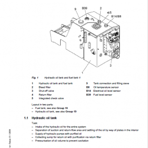
– 19. Arrangement of Tanks (Page 1999)
– 19.10 Tank Configuration A/R 310 from 101 (Page 2001)
– 19.15 Tank Configuration A/R 312 from 101 (Page 2005)
Be the first to review “Liebherr R308 Hydraulic Excavator Operators Service Repair Manual”
You must be logged in to post a review.
Reviews
There are no reviews yet.