
Liebherr R964 C Hydraulic Excavator Operators Service Repair Manual
Price range: $22.00 through $36.00
Manual Included:
PIN/Type – 448, 1008, 1009, 1126, 1145, 1165, 1278, 1300, 1364, 1370, 1377, 1416, 1447, 1448, 1503, 1651
- Service Repair Manual: 886 Pages
- Operators Manual (SN 16436: 22611) – 328 Pages
- Operators Manual (SN 22612: 27699) – 358 Pages
- Operators Manual (SN 27700: 30835) – 391 Pages
- Operators Manual (SN after 30836): 364 Pages
Specifications:
- Type: Excavator
- Model: R964 C
- PIN/Type: 448, 1008, 1009, 1126, 1145, 1165, 1278, 1300, 1364, 1370, 1377, 1416, 1447, 1448, 1503, 1651
- Manuals: Operators Manual, Repair Manual
- Language: English
- Format: PDF
- Description
- Additional information
- Reviews (0)
Description
Table of Content – Liebherr R964 C Hydraulic Excavator Type 448, 1008, 1009, 1126, 1145, 1165, 1278, 1300, 1364, 1370, 1377, 1416, 1447, 1448, 1503, 1651 Manual
- Front page
- Contents
- Introduction
- 1 General information
- 1.10: Safety instructions
- 1.20: Standards and regulations
- 1.50: Lubricants and operating fluids
- 1.60: Conservation guidelines
- 2 Tools
- 2.01: Special tools for maintenance and repair
- 2.02: Special tools for Liebherr Diesel engines
- 2.02:
- 2.03: Special tools for the hydraulic system
- 2.06: Special tools for electrical connectors
- 2.07: Special tools for gears
- 2.08: Common tools
- 2.10: Measuring tool for spool travel
- 2.12: Mounting tools for hydraulic cylinders
- 2.14: Wrench for the slotted nut on the swing gear SAT
- 2.15: Compression device for brake piston of gear SAT
- 2.16: Compression device for brake piston of gear FAT – construction line A
- 2.18: Compression device for brake piston of gear FAT – construction line P(r)
- 2.19: Tools for installing the slipring seals
- 3 Technical data / Maintenance guidelines
- 3.10: Technical data
- 3.12: Technical data
- 3.50: Control and maintenance chart
- 3.60: Control and maintenance chart
- 3.70: Lubrication chart
- 3.75: Lubrication chart
- 4 Engine / Motor
- 4.10: Technical Data Diesel Engines
- 5 Coupling / Splitterbox
- 5.10: Coupling
- 5.50: Pump distribution gear – construction line MKA 350 C
- 6 Hydraulic system
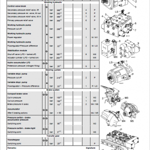
- 6.10: Adjustment Check List
- 6.20: Adjustment Check List
- 6.50: Hydraulic system description
- 6.70: Hydraulic Schematics – Components List
- 6.75: Hydraulic Schematics – Components List
- 6.90: List of hydraulic schematics – Standard execution
- 7 Hydraulic components
- 7.06: Pumps assembly R964C – R974C
- 7.13: LPV variable-displacement pump
- 7.17: Variable-displacement pump A4 VG
- 7.20: Hydraulic motors schedule
- 7.22: FMF hydraulic fixed displacement motor
- 7.27: FMV variable displacement hyd. motor
- 7.31: Hydraulic cylinders
- 7.32: Installations for pistons and piston nuts by hydraulic cylinders
- 7.35: Extension and retraction speeds
- 7.36: List of the hydraulic cylinders
- 7.37: List of the hydraulic cylinders
- 7.45: Regulating and servo oil unit
- 7.75: 1-way rotary connection
- 7.77: 5-way rotary connection
- 7.90: Line break safety valve
- 7.98: Hydraulic brake valve for travel motor
- 8 Electrical system
- 8.10: Construction of the electrical system
- 8.30: Monitoring display
- 8.80: Component list – Electrical diagrams
- 8.90: List of electrical diagrams – Standard execution
- 9 Swing gear
- 9.05: Swing gears – schedule
- 9.10: Technical data of the swing gears SAT
- 9.20: Swing Gear SAT – Function
- 9.40: Gear SAT 400 /256 – Section view
- 9.45: Gear SAT 375 /253 – Section view
- 10 Swing ring
- 10.20: Single row ball swing ring
- 11 Travel gear
- 11.05: Gear types schedule
- 11.11: Technical data of the travel gears
- 11.20: Gear FAT of construction line P(r)
- 11.30: Gear FAT of construction line A
- 11.40: Removing and reinstalling the travel gears FAT
- 11.51: Sealing the gear – construction line P(r) and A
- 11.71: Travel brakes
- 11.75: Slipring seals
- 12 Track components
- 12.10: Track components of crawler excavators
- 12.28: List of the track components on R964C
- 12.30: Wear on the track components
- 12.32: Wear limits for chains
- 12.35: Wear limits for rollers
- 12.38: Wear limits for guide & sprocket wheels
- 12.40: Removal, installation of track components
- 12.50: Spring tension units – technical data
- 12.55: Spring tension unit preassembled
- 12.56: Tension unit with single spring loose
- 12.57: Tension unit with two tension springs loose
- 12.58: Grease tensioner and guide wheel unit
- 12.70: Track roller
- 12.77: Carrier roller (supported on both sides)
- 12.80: Slipring seals
- 13 Undercarriage
- 13.10: Undercarriage with adjustable track gauge
- 16 Options
- 16.20: Additional attachment AHS 11 with Tool Control
- 16.28: Rotating device (AS2)
- 16.30: Refuelling pump
- 16.36: Option demolition
- 16.40: Overload warning system
- 16.42: Overload warning system
- 16.48: Stick and hoist cylinder shut-down
- 16.91: List of diagrams
- 2
- 3
- 4
- 5
- 6
- 7
- 8
- 9
- 10
- 11
- 12
- 13
- 14
- 15
- 16
- 7
- 18
- 19
- 17 Cab / Heater / Air conditioning system
- 17.30: Auxiliary heating D5WS
- 17.50: Heating and air-conditioning system
- 18 Central lubrication
- 18.10: System with 2 progressive lubrication circuits
- 18.30: Research of breakdowns and propositions of solutions
- 18.51: Lubrication pump
- 18.61: Progressive distributor SX-E
- 18.66: Progressive distributor MX-F
- 18.81: Lube hoses repair instructions
Additional information
| PIN Type | Type 448 & 1008 & 1009 & 1126 & 1145 & 1165 & 1278 & 1300 & 1364 & 1370 & 1377 & 1416 & 1447 & 1448 & 1503 & 1651 |
|---|---|
| Manual | Service Repair Manual, Operators Manual (SN 16436 – 22611), Operators Manual (SN 22612 – 27699), Operators Manual (SN 27700 – 30835), Operators Manual (SN after 30836) |
Be the first to review “Liebherr R964 C Hydraulic Excavator Operators Service Repair Manual”
You must be logged in to post a review.
Reviews
There are no reviews yet.