

Liebherr R 900 C EDC Litronic Hydraulic Excavator Operators Service Repair Manual
Price range: $20.00 through $42.00
Manual Included:
PIN/Type – 1076
- Service Repair Manual: 1377 Pages
- Operators Manual: 254 Pages
Specifications:
- Type: Excavator
- Model: R 900 C EDC Litronic
- PIN/Type: 1076
- Manuals: Operators Manual, Repair Manual
- Language: English
- Format: PDF
- Description
- Additional information
- Reviews (0)
Description
Table of Content – Liebherr R 900 C EDC Litronic Hydraulic Excavator Type 1076 Manual
- Book I Section 1-7 (Page -1)
- Titel
- Preface
- Index
- Book II Section 8
- (Page -1)
- Titel
- Index
- 1 General Information
- 1.01 Standards and regulations
- 1.02 Changes and modifications to series
- 1.10 Safety instructions
- 1.21 Tightening torques for fittings
- 1.51 Fuels, lubricants and process chemicals
- 1.55 TE_ML05 lubricant list
- 1.56 TE_ML07 lubricant list
- 1.60 Conservation guidelines
- 2 Tools
- 2.01 Special tools – general information
- 2.02 Special tools for diesel engines
- 2.05 Special tools for hydraulic system
- 2.06 Special tools for electrical equipment
- 2.07 Special tools for gears
- 2.12 Assembly tools for hydraulic cylinders
- 2.13 Mounting device for piston rod bearings
- 2.14 Slotted nut wrench for slewing gear mechanism
- 2.15 Mounting device for multi-disk brake
- 2.16 Mounting device for travel gear
- 3 Technical Data / Maintenance Guidelines
- 3.12 Technical data
- 3.22 Maintenance and inspection schedule
- 3.30 Lubrication chart
- 3.44 Adjustment protocol V4.8 R 900 C EDC
- 3.75 Checking and adjusting tasks V4.8
- 4 Engine
- 4.05 Bleeding the fuel system
- 4.10 Technical data of diesel engines
- 4.25 Installation and check list
- 4.27 Liebherr diesel particle filter accessory kit
- 4.40 Datalogger version 2.3.00
- 4.41 Datalogger software version 2.3.09
- 5 Coupling / pump distribution gear
- 5.10 Coupling
- 6 Hydraulic system
- 6.01 LSC system
- 6.19 Design of hydraulic system
- 6.28 Hydraulic system with blade support
- 6.29 Hydraulic system
- 6.30 Hydraulic system with blade support
- 6.31 Hydraulic system
- 7 Hydraulic components
- 7.01 Hydraulic pumps – dismantling, installation and initial operation
- 7.06 DPVO 165 variable-displacement pump
- 7.20 FMF hydraulic fixed displacement motor
- 7.29 Regulating motor A6VE (travel drive)
- 7.30 Hydraulic cylinder
- 7.31 Extension and retraction times of hydraulic cylinders
- 7.32 Hydraulic double plunger cylinder
- 7.39 Control oil and regulating unit
- 7.46 4x pilot control unit for travel drive
- 7.49 Pilot control unit 4x
- 7.53 Control block LSC
- 7.60 Cooling unit
- 7.68 Leak oil check at control valve blocks
- 7.75 Rotary connection 1x
- 7.77 Rotary connection 5x
- 7.95 Accumulator
- 8 Electrical system
- 8.01 Overview of electrical symbols
- 8.02 Notes regarding the electrical system
- 8.09 Layout of components
- 8.33/E3 Electrical system (construction model)
- 8.75 Monitoring display from version 4.8/V4.8.1
- 8.79 Control panel
- 8.80 Error code list
- 8.82 Slip ring rotary connection
- 9 Slewing gear mechanism
- 9.10 Slewing gear mechanism
- 9.21 Slewing gear brake
- 9.25 Positioning slewing brake
- 10 Slewing ring
- 10.10 Slewing ring
- 11 Transmission
- 11.60 FAT 350 travel gear system
- 11.65 Travel brake
- 12 Axles / Track Components
- 12.60 Chassis / drive
- 12.64 Technical data / tightening torques
- 12.66 Wear of chassis parts
- 12.69 Wear limits – B60
- 12.72 Chain
- 12.75 Tensioning unit
- 12.78 Idler
- 12.81 Running roller
- 12.82 Idler
- 12.84 Support roller
- 12.86 Slide ring seal
- 16 Special equipment / accessory kits
- 16.02 Pipe fracture safety valve for stick cylinder
- 16.03 Pipe fracture safety valve for boom cylinders
- 16.06 Overload warning system
- 16.08 Switchable overload warning system
- 16.10 Tool management
- 16.14 Camera monitoring system
- 16.15 Hydraulic quick-change adapter
- 16.16 Boom cylinder protection system
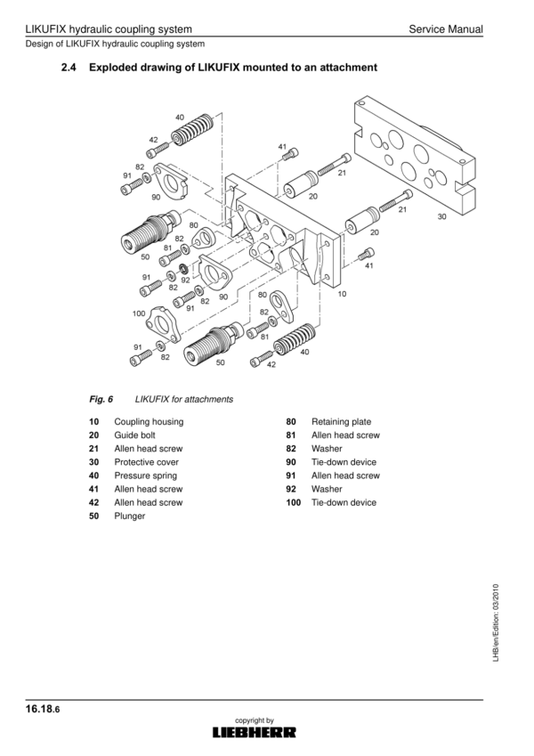
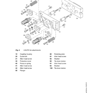
- 16.18 LIKUFIX hydraulic coupling system
- 16.19 Hydraulic-electric LIKUFIX coupling system
- 16.20 Pressure and flow reduction
- 16.22 Hydraulic hammer
- 16.23 Pipe layer
- 16.24 Swivel rotator TR-20/TR-25
- 16.40 Accessory kit AS1
- 16.43 Accessory kit AHS 1
- 16.46 AHS 11 accessory kit with Tool Control
- 16.48 Accessory kit AHS 12
- 16.49 AHS 12 accessory kit with Tool Control
- 16.54 AHS 11 proportional control
- 16.56 AHS 12 proportional control
- 16.58 Proportional control changeover AHS11/12
- 16.66 Refuelling pump
- 16.68 Bypass filter
- 16.69 LIEBHERR bypass filter
- 16.70 Reversible fan drive
- 16.71 Reversible fan drive (manual/automatic)
- 17 Cab / Heater / Air Conditioning System
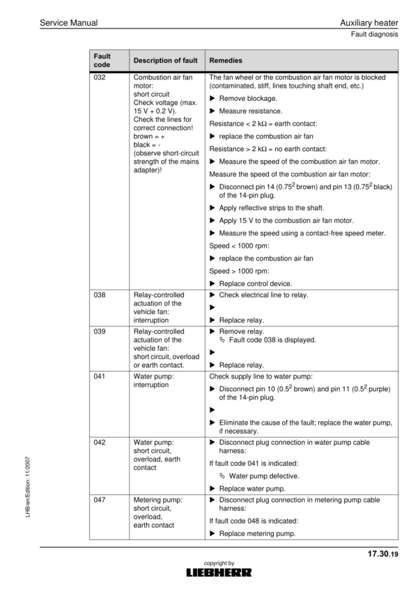
- 17.30 Auxiliary heater
- 17.40 Inspection and repair instructions for heating and air-conditioning system
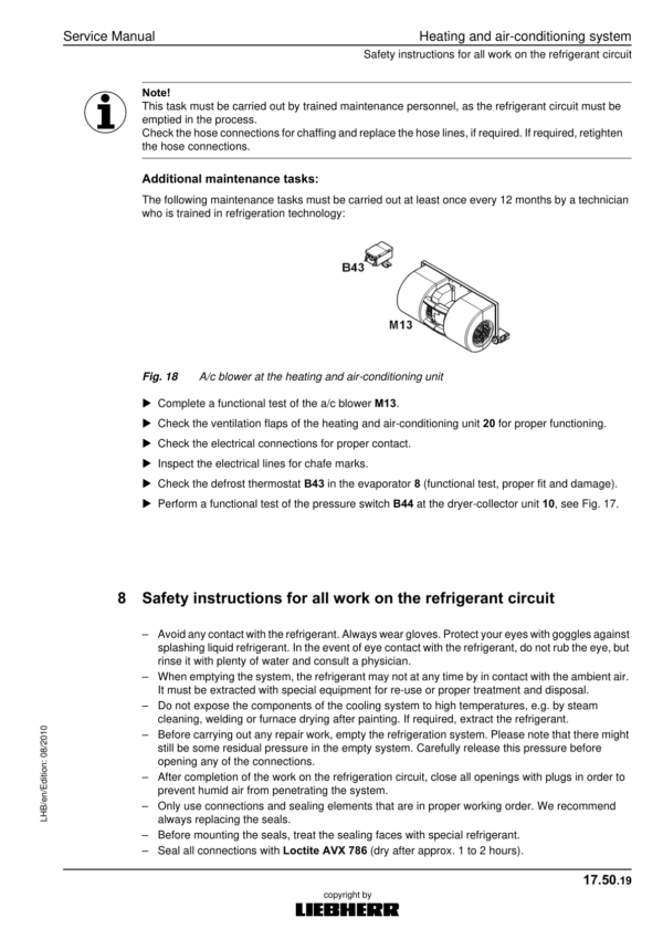
- 17.50 Heating and air-conditioning system
- 18 Undercarriage / uppercarriage / attachments
- 18.50 Repair instructions for lubrication hoses
- 18.53 Semi-automatic central lubrication system
- 18.54 Fully automatic central lubricating system
- 18.56 Central lubrication pump
- 18.58 SX-E progressive distributor
- 18.59 MX-F progressive distributor
Additional information
| PIN Type | Type 1076 |
|---|---|
| Manual | Service Repair Manual, Operators Manual |
Be the first to review “Liebherr R 900 C EDC Litronic Hydraulic Excavator Operators Service Repair Manual”
You must be logged in to post a review.
Reviews
There are no reviews yet.