
Liebherr LH80 M Hydraulic Excavator Operators Service Repair Manual
Price range: $22.00 through $52.00
Manual Included:
PIN/Type – 1205
- Service Repair Manual: 2034 Pages
- Operators Manual (US & Canada version): 354 Pages
- Operators Manual (High Rise Version): 330 Pages
- Operators Manual (Worldwide Version): 326 Pages
PIN/Type – 1218
- Service Repair Manual: 2696 Pages
- Operators Manual (US & Canada version): 404 Pages
- Operators Manual (High Rise Version): 396 Pages
- Operators Manual (Worldwide Version): 394 Pages
Specifications:
- Type: Excavator
- Model: LH80 M
- PIN/Type: 1205, 1218
- Manuals: Operators Manual, Repair Manual
- Language: English
- Format: PDF
- Description
- Additional information
- Reviews (0)
Description
Table of Content – Liebherr LH80 M Hydraulic Excavator Type 1205 Manual
- Book I Chapter 010 – 200
- 000.002 Preface
- 010 Introduction
- 010.005 Standards and regulations
- 010.010 New features and changes
- 010.020 Safety instructions
- 010.032 Tightening torques for fittings
- 010.043 Installation instructions: Mounting clamping nuts
- 010.050 Special tools, general
- 010.051 Special tools for hydraulic system
- 010.052 Special tools for electrical equipment
- 010.054 Special tools for slewing gearbox
- 010.059 Special tools for axles (Kessler)
- 010.060 Special tools, ERC cylinder
- 010.070 Preservation guidelines
- 010.071 Conservation of hydraulic cylinders
- 020 Technical data
- 020.010 Technical data LH 80 M
- 030 Maintenance
- 030.200 Maintenance LH80 M
- 030.400 Adjustment procedures from software 009
- 030.401 Adjustment procedures from software 023
- 030.410 Adjustment procedures from software 009
- 030.411 Adjustment procedures from software 023
- 040 Drive group
- 040.010 Technical data, diesel engine
- 040.020 Liebherr – diesel engine D936 A7 230kW – 270kW
- 040.022 Air filter system
- 040.035 Fuel system
- 040.060 Coupling
- 040.065 Liebherr diesel particulate filter
- 040.070 Pump distributor gear
- 050 Cooling system
- 050.010 Cooling system
- 050.020 Fan control
- 050.032 Reversible fan control
- 060 Working hydraulics
- 060.001 Overview of hydraulic symbols
- 060.002 Colour code of hydraulic schematics
- 060.003 Reducing pressure in the hydraulic system
- 060.010 Design of hydraulic system
- 060.020 Component list – hydraulic schematic
- 070 Travel hydraulics
- 070.025 FMV travel motor
- 070.065 A6V travel motor
- 080 Hydraulic components
- 080.015 Hydraulic tank
- 080.019 Putting into service hydraulic pumps
- 080.020 DPVP 165 double variable-displacement pump for ERC machines
- 080.025 A4 VG variable-displacement pump
- 080.030 A10V0 fan pump
- 080.040 Control oil unit
- 080.042 Servo control unit 4x (working functions)
- 080.044 Servo control unit 2x
- 080.050 M8 control block
- 080.060 FMF slewing gear motor
- 080.075 Rotary connection 9x
- 080.076 Rotary connection 5x
- 080.077 Rotary connection 1x
- 080.078 Rotary connection 6x
- 080.080 Hydraulic differential cylinder
- 080.085 Energy recuperation cylinder (ERC)
- 080.086 ERC expansion tank
- 080.087 ERC piston rod protection
- 080.090 Accumulator
- 080.100 Line break safety valve
- 090 Steering system
- 090.010 Hydraulic steering system
- 090.020 Joystick steering
- 100 Brake system
- 100.010 Hydraulic brake system
- 100.020 Compact brake block
- 110 Electrical system
- 110.001 Overview of electrical symbols
- 110.010 Operator's platform (wheeled machine)
- 110.022 Operator's platform (crawler)
- 110.023 Electrical system: uppercarriage
- 110.030 Electrical system: undercarriage
- 110.050 Circuit diagram: operator's platform
- 110.070 Circuit diagram: basic machine
- 110.075 Circuit diagram: diesel engine D936
- 110.085 Slip ring rotary connection
- 110.090 Malfunctions
- 110.095 Info menu – electrical inputs and outputs
- 120 Transmission / travel gearbox
- 120.010 W1650-2M transmission
- 120.021 Travel gearbox – series P(r)
- 120.022 Undercarriage pilot control valve
- 130 Axles / Drive
- 130.005 Oscillating axle support
- 130.020 Oscillating axle LT 102
- 130.022 Rigid axle D 102
- 130.030 Differential D 108 for axles LT 102 / D102
- 130.040 Intermediate axle gear D 51
- 130.046 Use of special tool (Kessler axles)
- 130.050 Travel gear / travel gear
- 130.052 Wear on running gear parts
- 130.053 Wear limits
- 130.054 Chain
- 130.055 Tensioning unit
- 130.056 Idler-wheel
- 130.057 Track roller
- 130.059 Carrier roller
- 130.060 Slip ring seal
- 140 Steel components – basic machine
- 140.010 Repair welding guideline
- 150 Working equipment
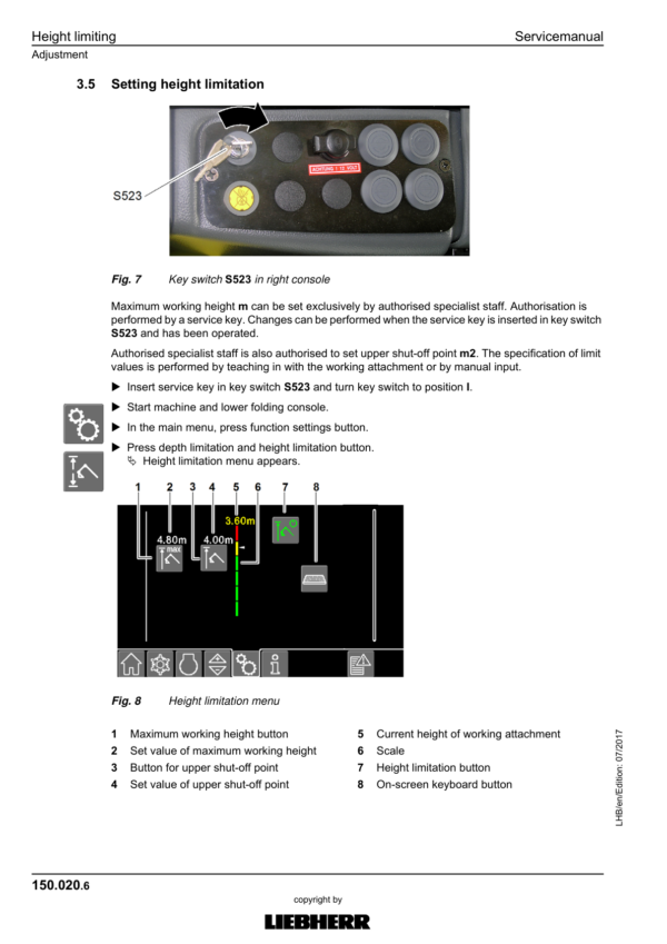
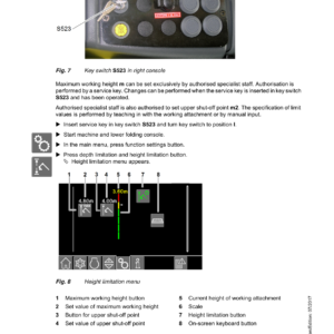
- 150.020 Height limiting
- 150.036 Outrigger support
- 150.037 Outrigger monitoring system
- 150.040 Hydraulic quick coupler
- 160 Operator's cab / heating / air-conditioning unit
- 160.001 Installation instruction for air-conditioning hose fittings
- 160.002 Mounting of operator's cab elevation
- 160.010 Height adjustable cab LHC 340/LHC 360
- 160.015 Height adjustable operator's cab
- 160.020 Hydraulically adjustable operator's cab, double joint cab (optional equipment)
- 160.030 Auxiliary heater
- 160.040 Air conditioning
- 160.045 Air-conditioning system service
- 170 Lubrication system
- 170.001 Repair instructions for lubrication hoses
- 170.010 Central lubrication system
- 170.030 SX-E progressive distributor
- 170.035 MX-F progressive distributor
- 180 Slewing gear mechanism / Slewing ring
- 180.010 Slewing gearbox
- 180.030 Slewing brake
- 180.032 Positioning slewing brake
- 180.050 Slewing ring
- 190 Equipment / Options
- 190.001 LiDAT remote diagnosis system
- 190.003 Hydraulic-electric coupling system
- 190.004 Check template for Likufix
- 190.006 Switchable overload warning system
- 190.010 Tool control
- 190.011 Grapple rotation
- 190.014 Tool Management
- 190.015 Reversible fan
- 190.030 Lifting boom when closing grapple
- 190.035 Generator drive accessory kit
- 190.040 High-pressure circuit 1 / AHS-11
- 190.045 High-pressure circuit 1 (AHS-11)
- 190.050 Changeover, high pressure circuit 1
- 190.055 Bypass filter
- 190.060 Hoist cylinder summation
- 190.065 Flow limitation
- 190.070 Control unit for pre-heating
- 190.072 Hydraulic oil pre-heating
- 190.074 Fuel preheating
- 190.076 Coolant pre-heating
- 190.078 Engine oil pre-heating
- 190.079 Hoist cylinder summation with flow limitation
- 190.081 Hoist cylinder summation
- 190.085 Pressure-free stick retraction
- 190.090 Stick extension shut-down
- 190.095 Stick retraction shut-down
- 190.110 Hoist cylinder shut-off
- 200 Diagnosis
- 200.005 Sculi variables editor
- 200.006 Sculi access to the variables
- 200.010 Checking and adjusting software wizard
- 200.020 Software update
- 200.030 Master module reset
- 200.035 CAN module addressing
- 200.038 CAN data transmission
Additional information
| PIN Type | Type 1205, Type 1218 |
|---|---|
| Manual | Service Repair Manual, Operators Manual (US & Canada version), Operators Manual (High Rise Version), Operators Manual (Worldwide Version) |
Be the first to review “Liebherr LH80 M Hydraulic Excavator Operators Service Repair Manual”
You must be logged in to post a review.
Reviews
There are no reviews yet.