

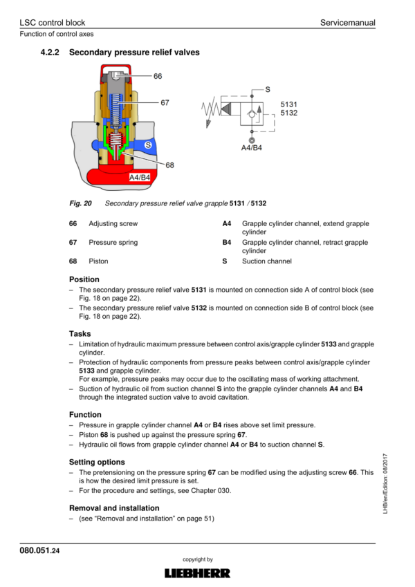
Liebherr LH26 EC Hydraulic Excavator Operators Service Repair Manual
Price range: $22.00 through $48.00
Manual Included:
PIN/Type – 1672
- Service Repair Manual: 1880 Pages
- Operators Manual: 362 Pages
PIN/Type – 1704
- Service Repair Manual: 1748 Pages
- Operators Manual: 578 Pages
Specifications:
- Type: Excavator
- Model: LH26 EC
- PIN/Type: 1672, 1704
- Manuals: Operators Manual, Repair Manual
- Language: English
- Format: PDF
- Description
- Additional information
- Reviews (0)
Description
Table of Content – Liebherr LH26 EC Hydraulic Excavator Type 1672 Manual
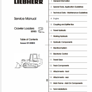
- Book I Chapter 010 – 200
- 000.002 Preface
- 010 Introduction
- 010.005 Standards and regulations
- 010.008 Component documentation
- 010.010 New features and changes
- 010.020 Safety instructions
- 010.043 Installation instructions: Mounting clamping nuts
- 010.050 Special tools, general
- 010.051 Special tools for hydraulic system
- 010.052 Special tools for electrical equipment
- 010.054 Special tools for slewing gearbox
- 010.056 Mounting device for multi-disc brake
- 010.058 Special tools for axles (ZF)
- 010.070 Preservation guidelines
- 010.071 Conservation of hydraulic cylinders
- 020 Technical data
- 020.001 Technical data
- 030 Maintenance
- 030.001 Maintenance
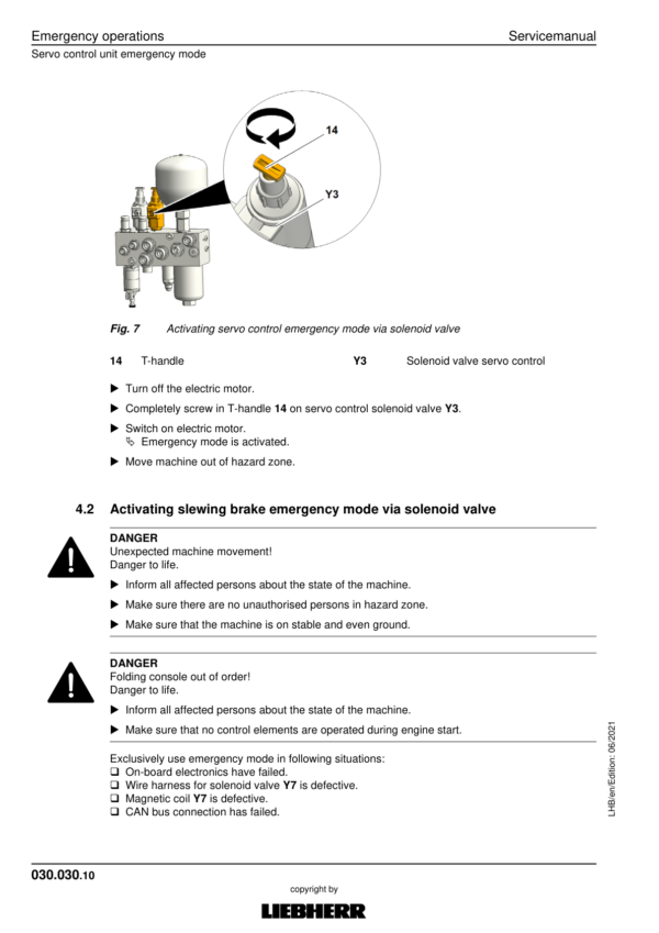
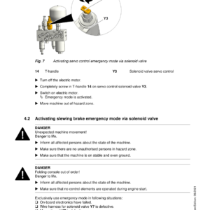
- 030.030 Emergency operations
- 030.051 Adjustment checklist LH26 EC
- 030.100 Preparations
- 030.105 Machine-specific data
- 030.110 Electric motor
- 030.115 Operating conditions
- 030.120 Servo control
- 030.126 Variable-displacement pump
- 030.131 Pump safety valve
- 030.135 Powertest
- 030.140 Control block, secondary pressures
- 030.146 Pressure cut-off valve for operating pressure
- 030.150 Slewing gear function
- 030.155 Hydraulic fan drive
- 030.160 Steering system
- 030.162 Travel function
- 030.165 Brake system
- 030.170 Transmission
- 030.175 Tool Control high pressure circuit 1
- 030.190 Cab control LHC 255 and LHC 255A
- 040 Drive group
- 040.020 Main drive, three-phase asynchronous motor
- 040.021 Auxiliary drive, three-phase asynchronous motor
- 040.055 Coupling
- 050 Cooling system
- 050.011 Cooling unit
- 050.020 Fan drive
- 050.030 Reversible fan drive
- 060 Working hydraulics
- 060.001 Overview of hydraulic symbols
- 060.002 Colour code of hydraulic schematics
- 060.003 Reducing pressure in hydraulic system
- 060.004 Bleeding hydraulic system
- 060.008 LSC system
- 060.020 Design of hydraulic system
- 060.040 Design of hydraulic system of crawler undercarriage
- 060.070 Hydraulic schematic LH22 C / LH26 EC
- 060.200 Hydraulic schematic, enabling travel
- 070 Travel hydraulics
- 070.006 Travel hydraulics: overview
- 070.015 DMVA O 165 travel motor
- 070.020 CMVE travel motor
- 080 Hydraulic components
- 080.015 Hydraulic tank
- 080.021 DPVO variable-displacement pump
- 080.040 Control oil unit
- 080.044 Pilot control unit / joystick
- 080.047 Pilot control unit 4x for travel drive
- 080.050 LSC control block
- 080.054 Control axis / slewing gear
- 080.055 Turning grapple
- 080.056 Auxiliary control axis, hydraulic two-piece boom
- 080.057 Auxiliary control axis, high pressure circuit 1 (HDK1)
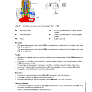
- 080.058 Servo control valves
- 080.059 Check for leak oil at control blocks
- 080.070 Slewing gear motor
- 080.075 Rotary connection 13x
- 080.077 Rotary connection 6x
- 080.080 Hydraulic differential cylinder
- 080.090 Accumulator
- 080.100 Line break safety valve
- 090 Steering system
- 090.010 Hydraulic steering system
- 090.020 Joystick steering
- 090.050 Installation, steering column with steering wheel
- 100 Branke system
- 100.010 Hydraulic brake system
- 100.020 Compact brake block
- 110 Electrical system
- 110.001 Overview of electrical symbols
- 110.002 Circuit diagrams in LIDOS
- 110.003 Connecting electric machine
- 110.004 Certified electrician work area
- 110.005 Overview of ground connections
- 110.020 Electrical system: operator's platform, wheeled
- 110.022 Electrical system: operator's platform, crawler
- 110.030 Electrical system: uppercarriage
- 110.040 Electrical system: undercarriage
- 110.052 Circuit diagram: operator's platform
- 110.060 Electrical system, uppercarriage 24V
- 110.100 Circuit diagram: TN system uppercarriage
- 110.102 Circuit diagram: TN system undercarriage
- 120 Travel gear mechanism
- 120.010 2 HL 270 / 290 transmission
- 120.022 Pilot control valve for transmission
- 120.050 Travel gearbox FAT 325/355
- 130 Axles / Drive
- 130.001 Tyres
- 130.003 Checking oscillating axle bearing for wear
- 130.005 Oscillating axle support
- 130.050 Travel gear / travel gear
- 130.051 Technical data and tightening torques
- 130.052 Checking travel gear components for wear
- 130.053 Wear limits of travel gear components
- 130.054 Chain
- 130.055 Tensioning unit
- 130.056 Idler-wheel
- 130.057 Track roller
- 130.059 Carrier roller
- 130.060 Slip ring seal
- 140 Steel parts – basic machine
- 140.010 Repair welding guideline
- 150 Working equipment
- 150.015 Boom, adjustable in vertical/horizontal direction
- 150.019 Stick cylinder shut-off
- 150.020 Height limiting
- 150.032 Support blade
- 150.034 Dozer blade
- 150.036 Outrigger support
- 150.037 Outrigger monitoring system
- 150.038 Stabiliser blade
- 150.040 Hydraulic quick coupler
- 150.042 Interface, third-party quick coupler
- 150.061 Manual changeover between bucket and grapple operation
- 150.062 Changeover between two-piece boom and high pressure circuit
- 150.063 Changeover between high pressure circuit 1 and bucket cylinder
- 160 Cab / heating / air conditioning
- 160.015 Height-adjustable cab LHC 255A
- 160.016 Tilting operator's cab
- 160.030 Stationary air conditioning
- 160.035 Heating and air conditioning unit
- 160.040 Air conditioning
- 160.045 Air conditioning diagnosis / service
- 170 Lubrication system
- 170.001 Repair of lubrication hose
- 170.005 Automatic central lubrication system
- 170.015 Central lubrication pump
- 170.025 Progressive distributor
- 170.050 Undercarriage lubricating pump
- 180 Slewing gear mechanism / Slewing ring
- 180.020 Slewing gearbox
- 180.030 Slewing brake
- 180.032 Positioning slewing brake
- 180.050 Slewing ring
- 190 Equipment / Options
- 190.001 LIDAT remote diagnosis system (LiTU2)
- 190.002 LiDAT: checking connection status
- 190.004 LiDAT remote diagnosis system (LiTU03)
- 190.005 LiDAT: creating a report and snapshot
- 190.007 Likufix coupling system
- 190.008 Check template for LIKUFIX
- 190.006 Switchable overload warning system
- 190.010 Tool control
- 190.012 High pressure circuit 1 summation
- 190.014 Tool Management
- 190.016 Deactivating hoist cylinder protection
- 190.022 Driver identification
- 190.035 SuperFinish
- 190.037 Generator drive accessory kit
- 190.050 Bypass filter in return filter
- 190.051 Dust intensive application
- 190.055 Bypass filter
- 190.090 Camera monitoring system
- 200 Diagnosis
- 200.005 Sculi variables editor
- 200.006 Sculi – access to the variables
- 200.010 Testing and adjustment software wizard
- 200.012 Accelerating starting time from Sculi Wizard
- 200.020 Software update
- 200.030 Master 4: Reset on master module
- 200.035 CAN module addressing
- 200.036 Master 4: Master module
- 200.038 CAN connections
- 200.090 Malfunctions
- 200.095 Information menu
- 200.100 Master 5: Reset to factory settings
- 200.102 Master 5: Connect "LiFT" function
- 200.104 Master 5: Software update
- 200.106 Master 5: Connect SCULi diagnostic software
- 200.108 Master 5: Service file
- 200.110 Master 5: Import license file
- 200.005 Sculi variables editor
- 200.006 Sculi – access to the variables
- 200.010 Testing and adjustment software wizard
- 200.012 Accelerating starting time from Sculi Wizard
- 200.020 Software update
- 200.030 Master 4: Reset on master module
- 200.035 CAN module addressing
- 200.036 Master 4: Master module
- 200.038 CAN connections
- 200.090 Malfunctions
- 200.095 Information menu
- 200.100 Master 5: Reset to factory settings
- 200.102 Master 5: Connect "LiFT" function
- 200.104 Master 5: Software update
- 200.106 Master 5: Connect SCULi diagnostic software
- 200.108 Master 5: Service file
- 200.110 Master 5: Import license file
Additional information
| PIN Type | Type 1672, Type 1704 |
|---|---|
| Manual | Service Repair Manual, Operators Manual |
Be the first to review “Liebherr LH26 EC Hydraulic Excavator Operators Service Repair Manual”
You must be logged in to post a review.
Reviews
There are no reviews yet.