
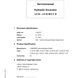
Liebherr LH22 C Hydraulic Excavator Operators Service Repair Manual
Price range: $22.00 through $56.00
Manual Included:
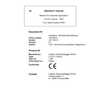
PIN/Type – 1209
- Service Repair Manual: 2536 Pages
- Operators Manual (US & Canada version): 328 Pages
- Operators Manual (Worldwide Version): 316 Pages
PIN/Type – 1525
- Service Repair Manual: 3742 Pages
- Operators Manual (US & Canada version): 392 Pages
- Operators Manual (Worldwide Version): 376 Pages
Specifications:
- Type: Excavator
- Model: LH22 C
- PIN/Type: 1209, 1525
- Manuals: Operators Manual, Repair Manual
- Language: English
- Format: PDF
- Description
- Additional information
- Reviews (0)
Description
Table of Content – Liebherr LH22 C Hydraulic Excavator Type 1209 Manual
- Book I Chapter 010 – 200
- 000.002 Preface
- 010 Introduction
- 010.005 Standards and regulations
- 010.010 New features and changes
- 010.020 Safety instructions
- 010.032 Tightening torques for fittings
- 010.043 Installation instructions: Mounting clamping nuts
- 010.050 Special tools, general
- 010.051 Special tools for hydraulic system
- 010.052 Special tools for electrical equipment
- 010.053 Special tools for diesel engines
- 010.055 Special tools for slewing gearbox
- 010.056 Mounting device for multi-disc brake
- 010.058 Special tools for axles (ZF)
- 010.070 Preservation guidelines
- 010.059 Special tools for axles (Kessler)
- 010.071 Conservation of hydraulic cylinders
- 020.050 Technical data LH 22 C
- 030.001 Fuels, lubricants and process chemicals
- 030.002 Filling quantities
- 030.010 Oil sampling for analysis
- 030.012 Inspection and maintenance schedule
- 030.045 Information on check and adjustment task
- 030.051 Checking and adjusting tasks for LH 22 C
- 040.010 Technical data of diesel engine
- 040.012 Technical data, diesel engine
- 040.020 Liebherr – diesel engine D934 A7 129 kW
- 040.021 Liebherr – diesel engine D934 A7 140kW – 175kW
- 040.022 D 834 diesel engine
- 040.031 Fuel system
- 040.033 Air filter unit
- 040.035 Exhaust gas system
- 040.060 Coupling
- 040.065 Liebherr diesel particulate filter
- 040.066 Liebherr diesel particle filter
- 040.070 Pump distributor gear
- 050.010 Cooling unit
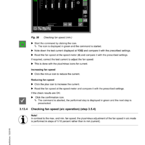
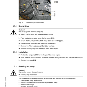
- 050.020 Fan control
- 050.030 Reversible fan control
- 060.001 Overview of hydraulic symbols
- 060.002 Colour code of hydraulic schematics
- 060.003 Reducing pressure in the hydraulic system
- 060.005 Design of hydraulic system
- 060.008 Design of hydraulic system LH22C/ LH26EC
- 060.009 Design of hydraulic system
- 060.012 Component list – hydraulic schematic
- 060.050 Component list – hydraulic schematic LH22C / LH26EC
- 060.055 Component list – hydraulic schematic
- 060.060 Component list, support variants
- 070.020 CMVE 085 hydraulic regulating motor
- 070.066 DMVA travel motor with EL/DA regulation
- 080.016 Hydraulic tank
- 080.020 Putting into service hydraulic pumps
- 080.021 DPVO variable-displacement pump
- 080.025 DPVP 108 double variable-displacement pump
- 080.040 Control oil unit
- 080.045 Servo control unit, 4 x (working functions)
- 080.047 Pilot control unit 4x for travel drive
- 080.050 LSC control block
- 080.051 Auxiliary control axle AS1 (medium pressure circuit)
- 080.053 Auxiliary control axle AHS11 (high pressure circuit)
- 080.055 LSC pilot plate
- 080.059 Check for leak oil at control valve blocks
- 080.070 Slewing gear motor
- 080.075 Rotary connection 13x
- 080.077 Rotary connection 6x
- 080.080 Hydraulic differential cylinder
- 080.090 Accumulator
- 080.100 Line break safety valve
- 090.010 Hydraulic steering system
- 090.020 Joystick steering
- 090.030 Four wheel steering
- 100.010 Hydraulic brake system
- 100.020 Compact brake block
- 110.001 Overview of electrical symbols
- 110.010 Operator's platform (wheeled machine)
- 110.022 Operator's platform (crawler)
- 110.023 Design of electrical system
- 110.050 Circuit diagram: operator's platform
- 110.062 Circuit diagram: basic machine
- 110.070 Circuit diagram of D834 diesel engine
- 110.080 Circuit diagram – diesel engine D934 A7 175 kW
- 110.083 Circuit diagram – diesel engine D934 A7 129 kW
- 110.085 Slip ring rotary connection
- 110.090 Malfunctions
- 110.095 Info menu – electrical inputs and outputs
- 120.010 2 HL 270 / 290 transmission
- 120.022 Undercarriage pilot control valve
- 120.050 Travel gearbox FAT 325/355
- 130.001 Tyres
- 130.003 Checking oscillating axle bearing for wear
- 130.005 Oscillating axle support
- 130.040 Oscillating axle LT 71 / LT 81
- 130.041 Rigid axle D 71 / D 81
- 130.042 Rigid axle LT 71 / LT 81, steered
- 130.046 Use of special tool (Kessler axles)
- 130.050 Travel gear / travel gear
- 130.051 Technical data / tightening torques
- 130.052 Wear on running gear parts
- 130.053 Wear limits
- 130.054 Chain
- 130.055 Tensioning unit
- 130.056 Idler-wheel
- 130.057 Track roller
- 130.059 Carrier roller
- 130.060 Slip ring seal
- 140.010 Repair welding guideline
- 150.019 Stick cylinder shut-off
- 150.020 Height limiting
- 150.032 Support blade
- 150.034 Dozer blade
- 150.036 Outrigger support
- 150.038 Stabiliser blade
- 150.040 Hydraulic quick coupler
- 150.042 Interface, third-party quick coupler
- 150.061 Manual changeover between bucket and grapple operation
- 160.001 Installation instruction for air-conditioning hose fittings
- 160.002 Mounting of operator's cab elevation
- 160.010 Height-adjustable cab LHC 255
- 160.012 Operator's cab with hydraulic adjustment
- 160.030 Auxiliary heater
- 160.040 Air conditioning
- 160.045 Air-conditioning system service
- 170.001 Repair instructions for lubrication hoses
- 170.010 Central lubrication system
- 170.030 SX-E progressive distributor
- 170.035 MX-F progressive distributor
- 180.010 Slewing gear mechanism
- 180.020 Slewing gearbox
- 180.030 Slewing brake
- 180.032 Positioning slewing brake
- 180.050 Slewing ring
- 190.001 LiDAT remote diagnosis system
- 190.003 Hydraulic-electric coupling system
- 190.004 Check template for Likufix
- 190.006 Switchable overload warning system
- 190.010 Tool control
- 190.014 Tool Management
- 190.016 Deactivating hoist cylinder protection
- 190.035 Generator drive accessory kit
- 190.036 SuperFinish
- 190.040 Mower rake accessory kit
- 190.050 Refuelling system
- 190.055 Bypass filter
- 190.070 Control unit for pre-heating
- 190.072 Hydraulic oil pre-heating
- 190.074 Fuel preheating
- 190.076 Coolant pre-heating
- 190.078 Engine oil pre-heating
- 200.005 Sculi variables editor
- 200.006 Sculi access to the variables
- 200.010 Checking and adjusting software wizard
- 200.020 Software update
- 200.022 Operator identification
- 200.025 Data logger
- 200.030 Master module reset
- 200.035 CAN module addressing
- 200.038 CAN data transmission
Additional information
| PIN Type | Type 1209, Type 1525 |
|---|---|
| Manual | Service Repair Manual, Operators Manual (US & Canada version), Operators Manual (Worldwide Version) |
Be the first to review “Liebherr LH22 C Hydraulic Excavator Operators Service Repair Manual”
You must be logged in to post a review.
Reviews
There are no reviews yet.