


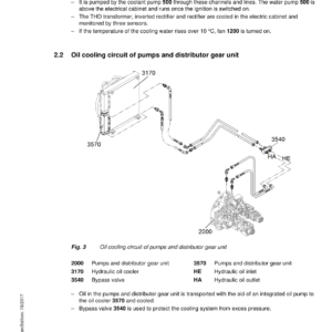
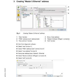
Liebherr LH150 EC Hydraulic Excavator Operators Service Repair Manual
Price range: $22.00 through $48.00
Manual Included:
PIN/Type – All
- Service Repair Manual: 1874 Pages
- Operators Manual (High Rise Version) – 368 Pages
- Operators Manual (SN after 126557) – 390 Pages
- Operators Manual (SN between 80820 – 126556) – 366 Pages
- Operators Manual (SN between 71308 – 80820) – 366 Pages
Specifications:
- Type: Excavator
- Model: LH150 EC
- PIN/Type: All
- Manuals: Operators Manual, Repair Manual
- Language: English
- Format: PDF
- Description
- Additional information
- Reviews (0)
Description
Table of Content – Liebherr LH150 EC Hydraulic Excavator Manual
- Book I Chapter 010 – 200
- 000.002 Preface
- 010 Introduction
- 010.001 New features and changes
- 010.005 Standards and regulations
- 010.008 Component documentation
- 010.020 Safety instructions
- 010.043 Installation instructions: Mounting clamping nuts
- 010.050 Special tools, general
- 010.051 Special tools for hydraulic system
- 010.052 Special tools for electrical equipment
- 010.060 Special tools, ERC cylinder
- 010.070 Prescriptions de conservation
- 010.071 Conservation of hydraulic cylinders
- 020 Technical data
- 020.001 Technical data
- 030 Maintenance
- 030.001 Maintenance
- 030.051 Adjustment checklist LH150 EC
- 030.100 Preparations
- 030.105 Machine-specific data
- 030.110 Electric motor
- 030.115 Operating conditions
- 030.120 Servo control
- 030.125 Variable-displacement pump P1 to variable- displacement pump P4
- 030.130 Primary pressure relief valve
- 030.141 Control block, secondary pressures
- 030.150 Slewing gear function
- 030.155 Hydraulic fan drive, fan circuit 2
- 030.161 Travel function
- 030.180 Medium pressure circuit
- 030.185 Turning grapple
- 030.190 Cab control triple joint
- 030.195 Generator drive
- 030.200 ERC cylinder
- 040 Drive group
- 040.020 Auxiliary drive, three-phase asynchronous motor
- 040.055 Coupling
- 040.060 Pump distributor gear PVG 450 D
- 050 Cooling system
- 050.010 Cooling units
- 050.022 Fan drive
- 050.030 Reversible fan drive
- 060 Working hydraulics
- 060.001 Overview of hydraulic symbols
- 060.002 Colour code of hydraulic schematics
- 060.003 Reducing pressure in the hydraulic system
- 060.020 Design of uppercarriage hydraulic system
- 060.040 Design of hydraulic system of undercarriage
- 060.045 Design of hydraulic system of MCR undercarriage
- 060.070 Hydraulic schematic LH150 EC
- 060.200 Hydraulic schematic / turning grapple
- 060.205 Hydraulic schematic of standard fan drive
- 060.210 Hydraulic schematic of reversible fan drive
- 060.215 Hydraulic schematic of generator drive
- 060.220 Hydraulic schematic: generator drive for Likufix
- 060.225 Hydraulic schematic of grapple pressure reduction
- 060.230 Hydraulic schematic, undercarriage Albatros
- 060.235 Hydraulic schematic, undercarriage MCR
- 060.240 Hydraulic schematic, return tank preloaded
- 070 Travel hydraulics
- 070.025 FMV travel motor
- 070.026 Travel brake valve for travel motor FMV
- 080 Hydraulic components
- 080.015 Hydraulic tank
- 080.020 Variable-displacement pump DPVO 165
- 080.025 Slewing gear pump DPVG 250
- 080.040 Control oil unit
- 080.050 Control block positive control / boom block
- 080.051 Control block positive control / stick block
- 080.060 FMF slewing motor
- 080.075 Rotary connection 6x
- 080.076 Rotary connection 5x
- 080.080 Hydraulic differential cylinder
- 080.085 Energy recuperation cylinder (ERC)
- 080.086 ERC expansion tank
- 080.087 ERC piston rod protection
- 080.090 Accumulator
- 080.100 Line break safety valve
- 110 Electrical system
- 110.001 Overview of electrical symbols
- 110.002 Circuit diagrams in LIDOS
- 110.004 Certified electrician work area
- 110.005 Overview of ground points
- 110.020 Electrical system: uppercarriage
- 110.024 Electrical system: undercarriage
- 110.050 Electrical system – Operator workplace 24V
- 110.060 Electrical system – Uppercarriage 24V
- 110.070 Electrical system – Undercarriage
- 110.072 Electrical system, undercarriage 24 V
- 110.080 Electrical system – Low voltage 690V
- 110.100 Electrical system – Low voltage 460V
- 110.103 Circuit diagram: TN system uppercarriage
- 110.104 Circuit diagram: TN system undercarriage
- 110.105 Electrical system, roller deflection
- 110.110 Electrical system, rail wheel pliers
- 110.115 Electrical system, motor cable drum
- 110.120 Electrical system, preheatings
- 110.125 Electrical system, WOKO magnet system
- 110.140 Electrical components adjustment procedures
- 110.200 Pilot control unit / joystick
- 120 Transmission / Travel gearbox
- 120.010 Travel gearbox FAT 550
- 120.020 Travel brake
- 130 Axles / Drive
- 130.050 Travel gear
- 130.055 Technical data and tightening torques
- 130.060 Checking travel gear components for wear
- 130.065 Wear limits of travel gear components
- 130.070 Chain
- 130.080 Idler
- 130.085 Track roller
- 130.090 Carrier roller
- 130.095 Slip ring seal
- 140 Steel components – basic machine
- 140.010 Repair welding guideline
- 150 Working attachment
- 150.040 Hydraulic quick coupler
- 150.041 Hydraulic quick coupler, industrial stick
- 160 Operator's cab / heating / air-conditioning unit
- 160.001 Installation instruction for air-conditioning hose fittings
- 160.002 Mounting of operator's cab elevation
- 160.010 Height adjustable operator's cab
- 160.030 Stationary air conditioning
- 160.040 Air conditioning system
- 160.045 Air conditioning diagnosis / service
- 170 Lubrication system
- 170.001 Repair of lubrication hose
- 170.005 Automatic central lubrication system
- 170.015 Central lubrication pump
- 170.025 Progressive distributor
- 170.050 Undercarriage lubricating pump
- 180 Slewing gearbox / Slewing ring
- 180.001 Slewing ring
- 180.010 Slewing gearbox SAT 450
- 180.020 Slewing brake
- 190 Equipment / Options
- 190.001 LiDAT remote diagnosis system
- 190.002 LiDAT: checking connection status
- 190.004 LiDAT remote diagnosis system (LiTU03)
- 190.005 LiDAT: creating a report and snapshot
- 190.030 Hydraulic oil pre-heating
- 190.055 Bypass filter
- 190.060 Control unit for pre-heating
- 190.090 Camera monitoring system
- 190.150 Watering device
- 200 Diagnosis
- 200.005 Sculi variables editor
- 200.006 Sculi – access to the variables
- 200.020 Software update
- 200.030 Master 4: Reset on master module
- 200.035 CAN module addressing
- 200.036 Master 4: Master module
- 200.038 CAN connections
- 200.090 Troubleshooting
- 200.095 Information menu
- 200.100 Master 5: Reset to factory settings
- 200.102 Master 5: Connect "LiFT" function
- 200.104 Master 5: Software update
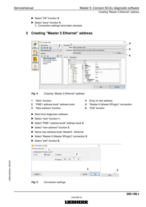
- 200.106 Master 5: Connect SCULi diagnostic software
- 200.108 Master 5: Service file
- 200.110 Master 5: Import license file
Additional information
| PIN Type | Type All |
|---|---|
| Manual | Service Repair Manual, Operators Manual (High Rise Version), Operators Manual (SN after 126557), Operators Manual (SN between 80820 – 126556), Operators Manual (SN between 71308 – 80820) |
Be the first to review “Liebherr LH150 EC Hydraulic Excavator Operators Service Repair Manual”
You must be logged in to post a review.
Reviews
There are no reviews yet.