
Liebherr D9508 A7 SCR Diesel Engine Service Repair Manual
Price range: $38.00 through $40.00
Manual Included:
- Service Handbook Manual: 176 Pages
- Service Manual:
Option 1 – Serial number between 2011140001 – 2012139999 (362 Pages)
Option 2 – Serial number after 2012140001 – (182 Pages) & Operators Manual (118 Pages)
Specifications:
- Brand: Liebherr
- Model: D9508 A7 SCR
- Type: Diesel Engine
- Manuals: Service Repair Manual
- Language: English
- Format: PDF
- Description
- Additional information
- Reviews (0)
Description
Table of Content (SN 2011140001 – 2012139999, D9508 A7 SCR Manual)
1 General information
1.1 Layout of this manual
1.2 Important notes within this manual
1.3 Symbols in this manual
1.4 Notes on safety
1.5 Notes regarding working on the fuel system and injection system
1.6 Notes on safety for working on the exhaust after-treatment system (SCR system)
1.7 Representations of the engine and engine components
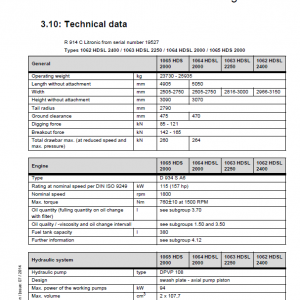
1.8 Technical data
1.9 Standard torques for screw connections
1.10 Special torques, tightening specifications and installation specifications
1.11 Diagram of the fuel system
1.12 Diagram of lube oil system
1.13 Diagram of coolant system
1.14 Charge air schematic
1.15 Allocation of ducts in the crankcase and in the cylinder head
1.16 Tools
2 Cylinder head, engine control and valves
2.1 Dismantling and installing the cylinder head cover
2.2 Dismantling and installing the rocker arm support and push rods
2.3 Dismantling and installing the valve fitting
2.4 Dismantling and installing the cylinder head
2.5 Dismantling and installing the valve stem seals, valve springs and valves
2.6 Dismantling and installing the roller tappet
2.7 Dismantling and installing the camshafts
2.8 Dismantling and installing the camshaft bearing
3 Engine
3.1 Dismantling and installing the piston with connecting rod and piston rings
3.2 Dismantling and installing the cylinder liner
3.3 Dismantling and installing the crankshaft accessories
3.4 Dismantling and installing the front crankshaft seal
3.5 Dismantling and installing the aggregate carrier
3.6 Assembly of the idler
3.7 Dismantling and installing the flywheel
3.8 Dismantling and installing the rear crankshaft seal
3.9 Dismantling and installing the crankshaft gear wheel
3.10 Dismantling and installing the flywheel housing
3.11 Dismantling and installing the crankshaft
4 Fuel system and injection system
4.1 Notes regarding working on the fuel system and injection system
4.2 Dismantling and installing the fuel lines
4.3 Dismantling and installing the injection lines
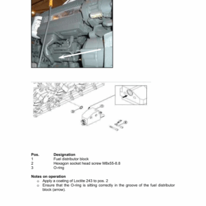
4.4 Installing and dismantling the pressure pipe tube and injector
4.5 Dismantling and installing the fuel fine filter module
4.6 Dismantling and installing the high-pressure pump
4.7 Dismantling and installing the drive for the high-pressure pump
5 Belt drive
5.1 Dismantling and installing the ribbed V-belt tensioning device and deflection pulley
6 Charge air and exhaust system
6.1 Dismantling and installing the exhaust pipe
6.2 Dismantling and installing the exhaust manifold
6.3 Dismantling and installing the exhaust turbocharger
6.4 Dismantling and installing the exhaust stack
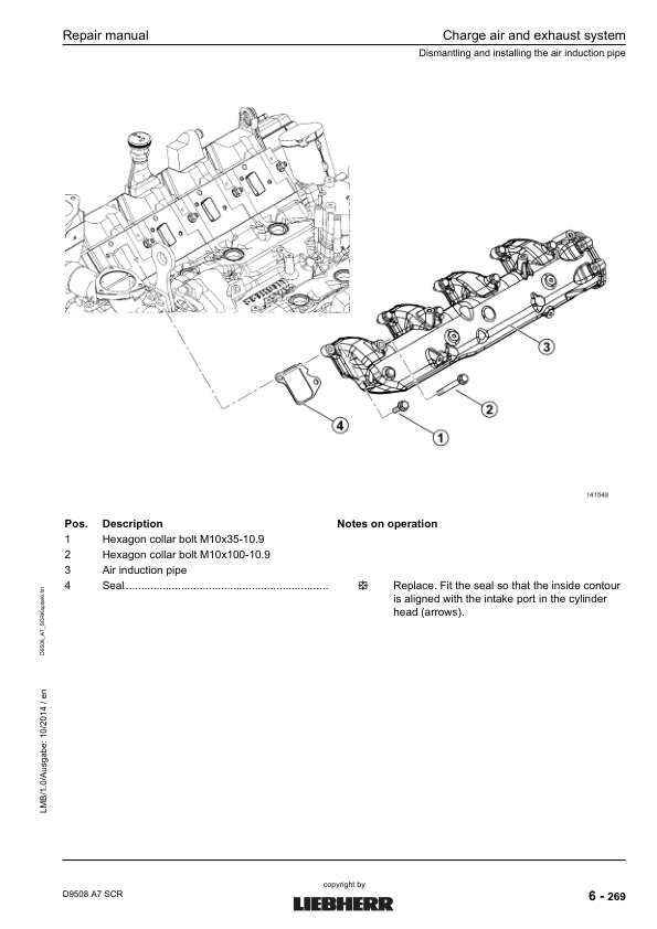
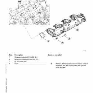
6.5 Dismantling and installing the air induction pipe
6.6 Dismantling and assembling the connecting line – flywheel side
6.7 Dismantling and installing the connecting line – aggregate carrier side
6.8 SCR-exhaust after-treatment system
7 Electrical system
7.1 Dismantling and installing the heater flange
7.2 Dismantling and installing the generator
7.3 Dismantling and installing the starter
7.4 Dismantling and installing the engine control unit
7.5 Dismantling and installing the sensors
7.6 Replacing the cable harness
8 Lubrication system
8.1 Dismantling and installing the final regulating valve
8.2 Dismantling and installing the crankcase breather
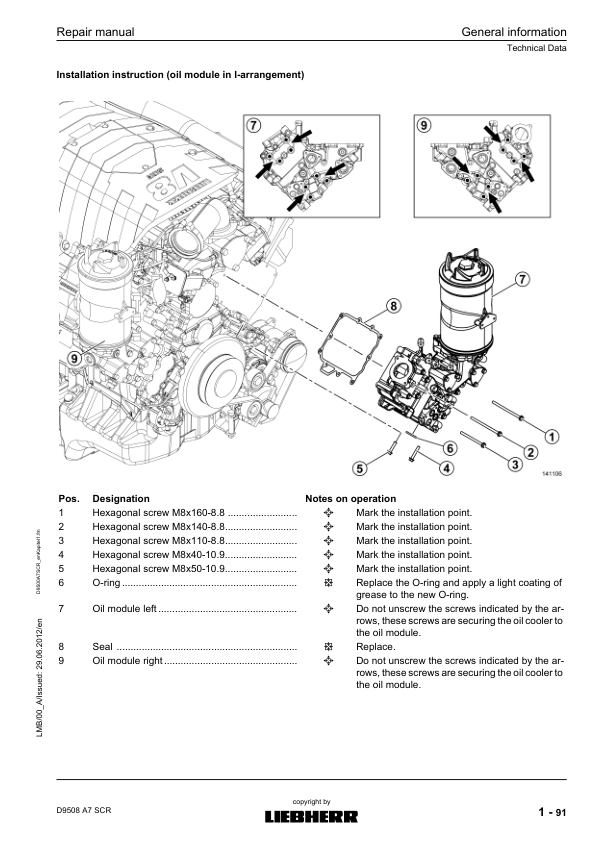
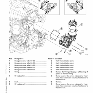
8.3 Dismantling and installing the oil module
8.4 Dismantling and installing the oil cooler
8.5 Dismantling and installing the oil sump
8.6 Dismantling and installing the lube oil pump
8.7 Dismantling and installing the piston cooling
9 Cooling system
9.1 Dismantling and installing the vent line
9.2 Dismantling and installing the coolant manifold
9.3 Dismantling and installing the thermostat housing
9.4 Dismantling and installing the thermostats
9.5 Checking the thermostat
10 Power take-off, air-conditioning compressor, fan
10.1 Dismantling and installing power take-off 1
10.2 Dismantling and installing power take-off 2
10.3 Dismantling and installing the wear parts for power take-offs
10.4 Dismantling and installing the air-conditioning compressor
10.5 Dismantling and installing the air compressor and air compressor mount
10.6 Dismantling and installing the fan and the fan drive
Additional information
| Option | SN 2011140001 – 2012139999 + Service Handbook, SN after 2012140001 + Operators Manual + Service Handbook |
|---|
Be the first to review “Liebherr D9508 A7 SCR Diesel Engine Service Repair Manual”
You must be logged in to post a review.
Reviews
There are no reviews yet.