
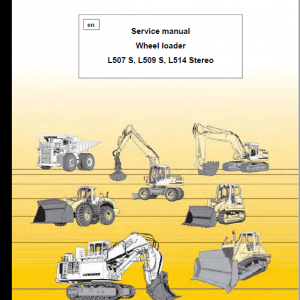
Liebherr R914 C Hydraulic Excavator Operators Service Repair Manual
Price range: $22.00 through $36.00
Manual Included:
PIN/Type – 1062, 1063, 1064, 1065
- Service Repair Manual: 876 Pages
- Operators Manual (SN 19527: 23078) – 380 Pages
- Operators Manual (SN 23079: 27781) – 373 Pages
- Operators Manual (SN after 27782): 371 Pages
Specifications:
- Type: Excavator
- Model: R914 C
- PIN/Type: 1062, 1063, 1064, 1065
- Manuals: Operators Manual, Repair Manual
- Language: English
- Format: PDF
- Description
- Additional information
- Reviews (0)
Description
Table of Content – Liebherr R914 C Hydraulic Excavator Type 1062, 1063, 1064, 1065 Manual
- Front page
- Contents
- Introduction
- 1 General information
- 1.10: Safety instructions
- 1.20: Standards and regulations
- 1.50: Lubricants and operating fluids
- 1.60: Conservation guidelines
- 2 Tools
- 2.01: Special tools for maintenance and repair
- 2.02: Special tools for Liebherr Diesel engines
- 2.03: Special tools for the hydraulic system
- 2.06: Special tools for electrical connectors
- 2.07: Special tools for gears
- 2.08: Common tools
- 2.10: Measuring tool for spool travel
- 2.12: Mounting tools for hydraulic cylinders
- 2.14: Wrench for the slotted nut on the swing gear SAT
- 2.15: Compression device for brake piston of gear SAT
- 2.17: Compression device for brake piston of gear FAT – construction line P(b)
- 2.19: Calibration values for LMS system
- 2.22: Tools for installing the slipring seals
- 3 Technical data / Maintenance guidelines
- 3.10: Technical data
- 3.12: Technical data
- 3.50: Control and maintenance chart
- 3.70: Lubrication chart
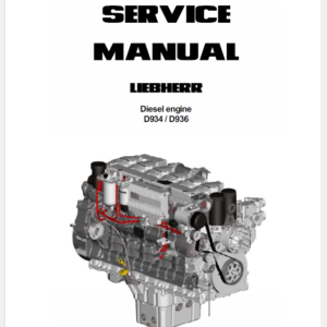
- 4 Engine / Motor
- 4.10: Technical data for LIEBHERR Engine Type: D 934 S A6
- 4.26: Installation and check list for Diesel particle filter
- 4.27: Liebherr Diesel particle filter (accessory kit)
- 4.40: Datalogger
- 5 Coupling / Splitterbox
- 5.10: Coupling
- 5.30: Pump distribution gear – construction line DPVP
- 6 Hydraulic system
- 6.63: Adjustment Check List
- 6.64: Adjustment Check List
- 6.68: Load Sensing Control
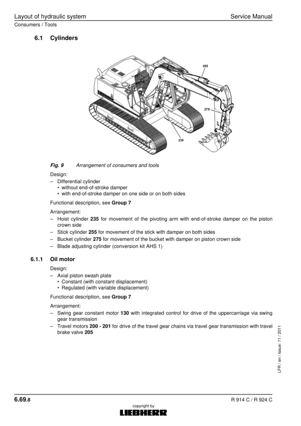
- 6.69: Layout of hydraulic system
- 6.80: Hydraulic Schematics – Components List
- 6.90: List of hydraulic schematics – Standard executions
- 7 Hydraulic components
- 7.01: Hydraulic pump: Removal, installation, Start-up.
- 7.11: Variable-displacement twin pump DPVP
- 7.20: Hydraulic motors schedule
- 7.25: HMF 75-02P hydraulic fixed-displacement motor
- 7.30: Hydraulic cylinders
- 7.31: Extension and retraction speeds
- 7.32: Installations for pistons and piston nuts by hydraulic cylinders
- 7.38: Hydraulikzylinder – R 914 C / R 924 C
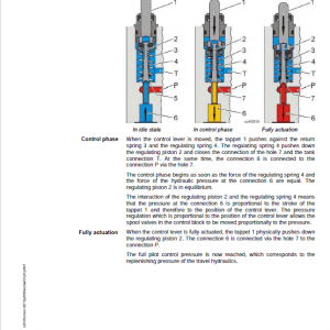
- 7.45: Control oil and control unit
- 7.50: 1-way servo control
- 7.51: 2-way servo control
- 7.55: 4-way servo control (Rexroth)
- 7.56: Hydraulic pilot control device with 2 pedals and damping system
- 7.61: Control valve complete
- 7.62: Control plate
- 7.64: Inspecting the control valve blocks for leak oil
- 7.75: 1-way rotary connection
- 7.77: 5-way rotary connection
- 7.79: 7-way rotary connection
- 7.97: Brake valve for hydraulic travel gear motor
- 8 Electrical system
- 8.10: Construction of the electrical system
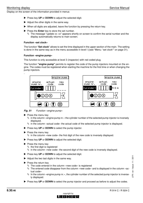
- 8.30: Monitoring display
- 8.40: Control unit S2
- 8.80: Component list – Electrical diagrams
- 8.90: List of electrical diagrams – Standard execution
- 9 Swing gear
- 9.10: Swing gear «SAT»
- 9.20: Swing gear brake
- 10 Swing ring
- 10.10: Ball slewing ring
- 11 Travel gear
- 11.10: Gear types schedule
- 11.15: Technical data of the travel gears
- 11.25: Travel gear FAT of construction line P(b)
- 11.50: Sealing the gear – construction line P(b)
- 11.71: Travel brakes
- 11.75: Slipring seals
- 12 Track components
- 12.10: Track components of crawler excavators
- 12.20: List of the track components on R 914C – R 924C
- 12.30: Wear on the track components
- 12.32: Wear limits for chains
- 12.35: Wear limits for rollers
- 12.38: Wear limits for guide & sprocket wheels
- 12.40: Dismantling and installing track components
- 12.52: Tension units – Technical data
- 12.56: Tension unit with single spring loose
- 12.58: Grease tensioner and guide wheel unit
- 12.70: Track roller
- 12.75: Carrier roller (supported on one side)
- 12.80: Slipring seals
- 16 Options
- 16.02: Load holding valves for Hoist Cylinders
- 16.20: Hydraulic installation kit AHS 11 with Tool Control
- 16.24: Hydraulic installation kit AHS 12 with Tool Control
- 16.30: Refuelling pump
- 16.91: List of diagrams
- 16.92: List of diagrams
- Hydraulic schematic
- Electrical schematic
- (Page -1)
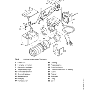
- 17 Cab / Heater / Air conditioning system
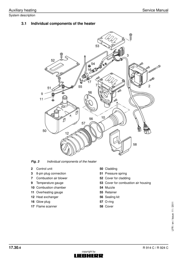
- 17.30: Auxiliary heating
- 17.50: Heating and air-conditioning system
- 18 Central lubrication
- 18.50: Lube hoses repair instructions
- 18.51: Centralized lubrication system
- 18.56: Pump of the centralized lubrication system
- 18.58: Progressive distributor SX-E
- 18.59: Progressive distributor MX-F
Additional information
| PIN Type | Type 1062 & 1063 & 1064 & 1065 |
|---|---|
| Manual | Service Repair Manual, Operators Manual (SN 19527 – 23078), Operators Manual (SN 23079 – 27781), Operators Manual (SN after 27782) |
Be the first to review “Liebherr R914 C Hydraulic Excavator Operators Service Repair Manual”
You must be logged in to post a review.
Reviews
There are no reviews yet.