
Liebherr D9508 A7-04 Diesel Engine Service Repair Manual
$37.00
Manual Included:
- Service Repair Manual: 362 Pages
- Operators Manual: 98 Pages & 206 Pages
Specifications:
- Brand: Liebherr
- Model: D9508 A7-04
- Type: Engine
- Manuals: Service Repair Manual & Operation Manual
- Language: English
- Format: PDF
- Description
- Reviews (0)
Description
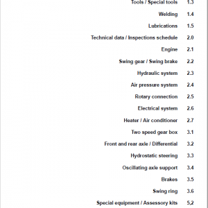
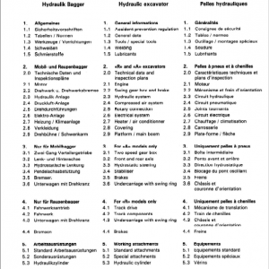
Table of Content D9508 A7-04 Service Manual
1 General information
1.1 Structure of these instructions
1.2 Important notes in these instructions
1.3 Safety instructions
1.4 Safety instructions for working on the fuel and injection system
1.5 Safety instructions for working on the exhaust after-treatment system (SCR system)
1.6 Engine diagrams and engine components
1.7 Technical data
1.8 Standard torques
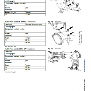
1.9 Special torques, tensioning instructions, instructions for mounting and installation instructions
1.10 Cleaning and locking agents, greases
1.11 Fuel diagram
1.12 Lubricating oil diagram
1.13 Coolant diagram
1.14 Charge air diagram
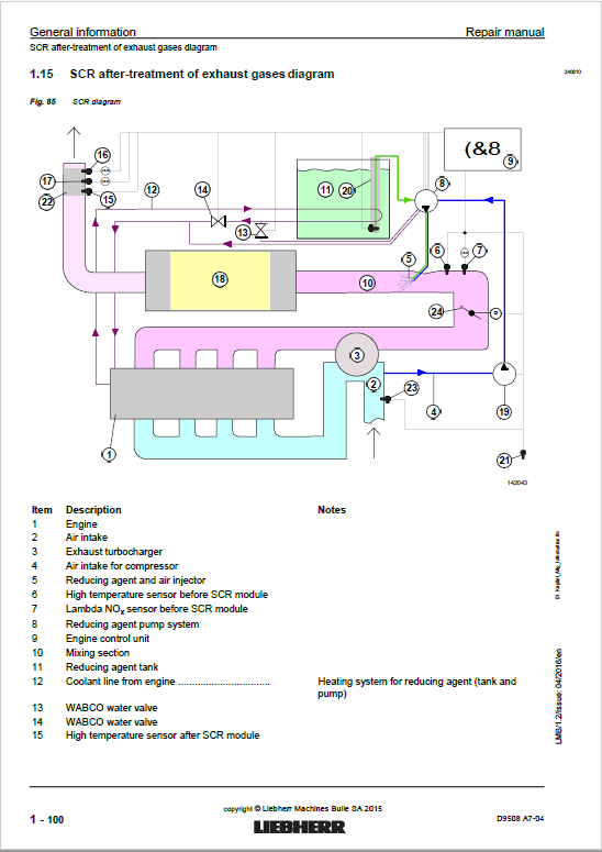
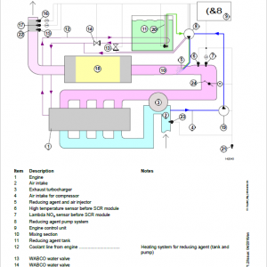
1.15 SCR after-treatment of exhaust gases diagram
1.16 Assigning the channels in the crankcase and the cylinder head
1.17 Transport device and fastening parts
1.18 Tools
2 Cylinder head, engine control unit and valves
2.1 Removing and installing the cylinder head cover
2.2 Removing and installing the rocker arm bracket and push rods
2.3 Removing and installing the valve bridge (engines with and without ABS)
2.4 Removing and installing the cylinder head
2.5 Removing and installing the valve stem seals, valve springs, valves
2.6 Removing and installing the roller tappet
2.7 Removing and installing the camshaft
2.8 Removing and installing the camshaft bearing
3 Driving gear
3.1 Removing and installing the piston with connecting rod and piston rings
3.2 Removing and installing the cylinder liner
3.3 Removing and installing the crankshaft attachments
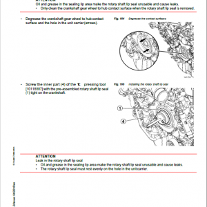
3.4 Removing and installing the front crankshaft seal
3.5 Removing and installing the unit carrier
3.6 Removing and installing the intermediate wheel
3.7 Removing and installing the flywheel
3.8 Removing and installing the rear crankshaft seal
3.9 Removing and installing the crankshaft gear wheel
3.10 Removing and installing the flywheel housing
3.11 Removing and installing the crankshaft
4 Fuel and injection system
4.1 Removing and installing the fuel lines
4.2 Removing and installing the injection line
4.3 Removing and installing the rail
4.4 Removing and installing the pressure pipe branch and injector
4.5 Removing and installing the fuel fine filter module
4.6 Removing and installing the high pressure pump
4.7 Removing and installing the high pressure pump drive
5 Belt drive
5.1 Removing and installing the V-ribbed belt tensioning device and deflection rollers
6 Charge air and exhaust system
6.1 Removing and installing the intake branch
6.2 Removing and installing the charge air line
6.3 Removing and installing the air intake
6.4 Removing and installing the connecting line
6.5 Removing and installing the air intake pipe
6.6 Removing and installing the exhaust branch
6.7 Removing and installing the charge air control unit
6.8 Removing and installing the exhaust turbocharger
6.9 Removing and installing the exhaust manifold
6.10 Removing and installing the exhaust pipe
6.11 SCR exhaust after-treatment system
6.12 Troubleshooting in SCR system
7 Electrical system
7.1 Removing and installing the heating flange
7.2 Removing and installing the alternator
7.3 Removing and installing the starter
7.4 Removing and installing the engine control unit
7.5 Removing and installing the engine control unit console
7.6 Removing and installing sensors
7.7 Replacing the cable harness
8 Lubrication system
8.1 Removing and installing the end control valve
8.2 Removing and installing the crankcase ventilation pipeline
8.3 Removing and installing the crankcase ventilation
8.4 Removing and installing the oil module
8.5 Removing and installing the oil cooler
8.6 Removing and installing the oil pan
8.7 Removing and installing the lubricating oil pump
8.8 Removing and installing the piston cooling
9 Cooling system
9.1 Removing and installing the ventilation line
9.2 Removing and installing the coolant manifold
9.3 Removing and installing the coolant pump
9.4 Removing and installing the thermostat housing
9.5 Removing and installing the thermostats
9.6 Check the thermostat
10 Auxiliary output, air conditioning compressor, fan
10.1 Removing and installing auxiliary output 1
10.2 Removing and installing auxiliary output 2
10.3 Removing and installing the locking pieces for the auxiliary outputs
10.4 Removing and installing the air conditioning compressor
10.5 Removing and installing the air compressor
10.6 Removing and installing the fan and fan drive
11 Appendix
11.1 Abbreviations used
This service handbook comprises a summary of the most important maintenance, adjustment and repair tasks, as well as details regarding technical data and tightening specifications for screws for Liebherr diesel engine D9508 A7-04 It is prerequisite that these tasks are performed by trained, specialist personnel.
The accident prevention regulations and all generally recognized safety and occupational health regulations are to be observed during all maintenance and repair work on Liebherr diesel engines. Observe the national regulations in the country and place of use if necessary.
Furthermore, the special safety instructions for diesel engines provided in the “Safety instructions” chapter must be observed.
Be the first to review “Liebherr D9508 A7-04 Diesel Engine Service Repair Manual”
You must be logged in to post a review.
Reviews
There are no reviews yet.