
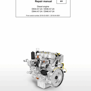
Liebherr D934 A7-24, D936 A7-24, D944 A7-24, D946 A7-24 Diesel Engine Service Repair Manual
$40.00
Manual Included:
- Service Repair Manual: 300 Pages
Specifications:
- Brand: Liebherr
- Model: D934 A7-24, D936 A7-24, D944 A7-24, D946 A7-24
- Type: Diesel Engine
- Manuals: Service Repair Manual
- Language: English
- Format: PDF
- Description
- Reviews (0)
Description
Table of Content (D934 A7-24, D936 A7-24, D944 A7-24, D946 A7-24 Repair Manual)
1 Safety
1.1 Safety instructions
1.2 Target group
1.3 Intended use
1.4 Limitation of liability
1.5 General safety instructions
1.6 Preventing personal injuries
1.7 Personal protective equipment
1.8 Operating and maintenance areas
1.9 Prevention of property damage
2 General information
2.1 Structure of this manual
2.2 Engine diagrams and engine components
2.3 Technical data
2.4 Fuel diagram
2.5 Lubricating oil diagram
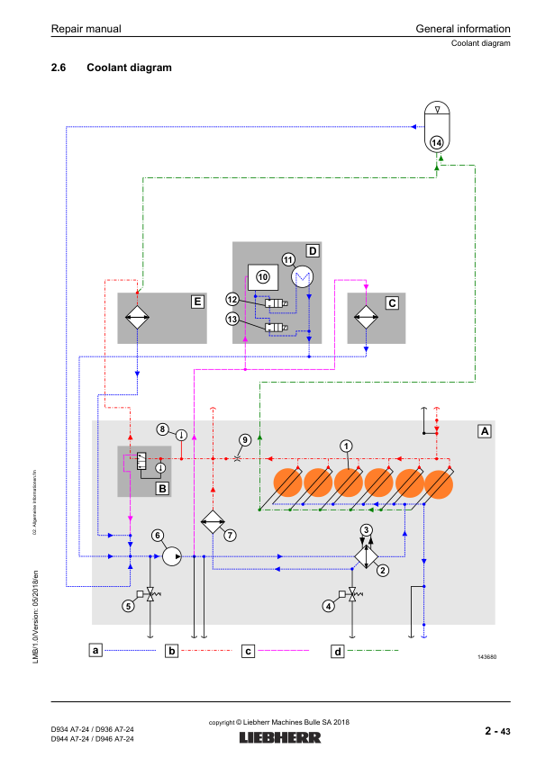
2.6 Coolant diagram
2.7 Assigning the channels in the crankcase and cylinder head
2.8 Transport device and fastening parts
3 Cylinder head, engine control unit and valves
3.1 Removing and installing cylinder head cover
3.2 Removing and installing rocker arm bracket and push rods
3.3 Removing and installing valve bridge (with/without ABS)
3.4 Removing and installing cylinder head
3.5 Removing and installing injector sleeve
3.6 Removing and installing valve stem seals, valve springs, valves
3.7 Removing and installing roller tappet (valve controller)
3.8 Removing and installing camshaft
4 Driving gear
4.1 Removing and installing piston with crank and piston rings
4.2 Removing and installing cylinder liner
4.3 Removing and installing crankshaft attachments
4.4 Removing and installing front crankshaft seal
4.5 Removing and installing unit carrier
4.6 Removing and installing flywheel
4.7 Removing and installing rear crankshaft seal
4.8 Removing and installing flywheel housing
4.9 Removing and installing top right intermediate wheel
4.10 Removing and installing top middle intermediate wheel
4.11 Removing and installing crankshaft
4.12 Removing and installing crankshaft gear wheel
5 Fuel and injection system
5.1 Safety instructions for working on the fuel and injection system
5.2 Removing and installing the fuel lines
5.3 Removing and installing the leakage oil lines
5.4 Removing and installing the injection lines
5.5 Removing and installing the rail
5.6 Removing and installing the pressure pipe branch and injector
5.7 Removing and installing the fuel fine filter with console
5.8 Removing and installing the fuel high pressure pump
5.9 Removing and installing the fuel high pressure pump drive
6 Belt drive
6.1 Overview of belt drives
6.2 Removing and installing the cover for belt drive I
6.3 Removing and installing the V-ribbed belt tensioning device
6.4 Removing and installing the V-ribbed belt deflection roller
6.5 Removing and installing belt drive II (A/C compressor variant II)
6.6 Removing and installing belt drive III (fan drive)
7 Charge air and exhaust system
7.1 Removing and installing the air intake
7.2 Removing and installing the air intake pipe
7.3 Removing and installing the suction port
7.4 Removing and installing the connection line (turbocharger – charge air cooler)
7.5 Removing and installing the heat protection plate
7.6 Removing and installing the exhaust branch
7.7 Removing and installing the turbocharger
7.8 Removing and installing the exhaust pipe
8 Lubrication system
8.1 Replacing the oil filter
8.2 Removing and installing the crankcase ventilation
8.3 Removing and installing the oil return line
8.4 Removing and installing the oil dipstick and guiding pipe
8.5 Removing and installing the oil pan
8.6 Removing and installing the oil pan attachments
8.7 Removing and installing the oil cooler housing with oil cooler
8.8 Removing and installing the oil pressure pump
8.9 Removing and installing the oil extraction pump (D936 / D946)
8.10 Removing and installing the locking pieces for the oil extraction pump (D936 / D946)
8.11 Removing and installing the piston cooling injector
8.12 Removing and installing the end control valve
9 Cooling system
9.1 Removing and installing the coolant ventilation line
9.2 Removing and installing the coolant pump
9.3 Removing and installing the coolant manifold
9.4 Removing and installing the thermostat housing and the thermostat
9.5 Removing and installing the 6-cylinder water collecting line
10 Auxiliary output, air compressor and A/C compressor
10.1 Overview of auxiliary drives
10.2–10.4 Removing and installing auxiliary output sealing parts (1–4)
10.5–10.8 Removing and installing auxiliary outputs (1–4)
10.9 Removing and installing the air compressor
10.10 Removing and installing the switchable auxiliary output on the flywheel housing
10.11 Dismantling the switchable auxiliary output for the spool repair kit
10.12 Dismantling and assembling the switchable auxiliary output bearing housing
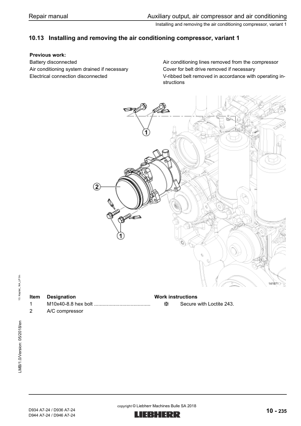
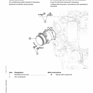
10.13 Installing and removing the air conditioning compressor, variant 1
10.14 Installing and removing the air conditioning compressor, variant 2
11 Electrical system
11.1 Removing and installing the alternator
11.2 Removing and installing the starter
11.3 Removing and installing the sensors
11.4 Removing and installing the engine control unit
11.5 Replacing the cable harness
12 Exhaust after-treatment system
12.1 Safety instructions for working on the exhaust after-treatment system
12.2 SCR exhaust after-treatment system
13 Annex
13.1 Standard torques
13.2 Cleaning and locking agents, greases
13.3 Tools
13.4 Terms used (Glossary)
13.5 Abbreviations used
Be the first to review “Liebherr D934 A7-24, D936 A7-24, D944 A7-24, D946 A7-24 Diesel Engine Service Repair Manual”
You must be logged in to post a review.
Reviews
There are no reviews yet.