
Liebherr A312 Hydraulic Excavator Operators Service Repair Manual
$40.00
Manual Included:
- Service Repair Manual: 2010 pages
- Operators Manual: 132 pages
Specifications:
- Type: Excavator
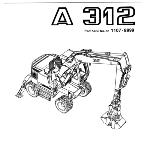
- Model: A312
- PIN/Type: All
- Manuals: Operators Manual, Repair Manual
- Publication Numbers: 8717977, 8717522
- Language: English
- Format: PDF
- Description
- Reviews (0)
Description
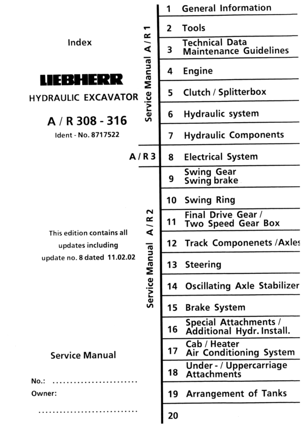
Table of Content – Service Repair Manual (A 312)
- Book I Group 1-7 (Page -1)
- Index (Page 1)
- Foreword (Page 3)
- Page index 1-7 (Page 5)
- Book II Group 8 (Page 17)
- Index (Page 17)
- Page Index 8 (Page 19)
- Book III Group 9-19 (Page 27)
- Index (Page 27)
- Page Index 9-19 (Page 29)
- 1. General Information (Page 43)
- 1.10 Safety Guidelines (Page 45)
- 1.20 Charts / Norms (Page 55)
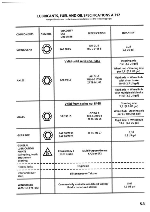
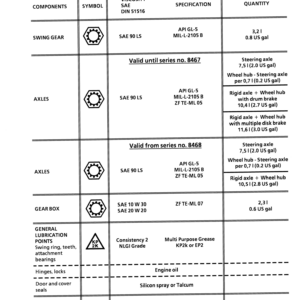
- 1.50 Service Fluids (Page 69)
- 1.55 Oil Specification Chart “LS-Oil” (Page 79)
- Tools (Page 85)
- 2.01 Listing of special tools for excavators (general) (Page 87)
- 2.03 Listing of special tools for Deutz Engine (Page 99)
- 2.05 Listing of special tools for hydraulic system (Page 119)
- 2.06 Listing of special tools for electrical connectors (Page 135)
- 2.07 Listing of special tools for gears (Page 145)
- 2.08 Listing of special tools for axles (Page 151)
- 2.10 Listing of special tools for Piston Wrech (Page 161)
- 2.11 Listing of special tools for Special assy spanner (Page 163)
- 2.12 Listing of special tools for Removal device (Page 165)
- 2.13 Listing of special tools for Ring nut spanner (Page 171)
- 2.14 Listing of special tools for Spool travel measuring tool (Page 173)
- 2.15 Listing of special tools for Testing device (Page 175)
- 2.16 Listing of special tools for Push out and centering pin (Page 177)
- 2.17 Listing of special tools for Intermiate plate (Page 179)
- 3. Technical Data / Maintenance Guidelines (Page 181)
- 3.14 Technical Data A 312 from 101 (Page 195)
- 3.24 Maintenance Guidelines A 312 from 101 (Page 217)
- 4. Engine (Page 223)
- 4.12 Engine BF 4 M 1012 E A/R 310 B from 1001 / A/R 312 from 101 (Page 237)
- 5. Clutch / Splitterbox (Page 245)
- 5.05 Elastic Coupling A/R 308 / A/R 310 / A/R 312 from 101 / A/R 310 B 1001 (Page 247)
- 5.10 Elastic Coupling A 312 from 861 / R 312 from 257 / A 316 from 101 (Page 251)
- 6. Hydraulic system (Page 255)
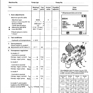
- 6.12.01 Hydraulic System Pressure Settings and Flow A 312 from 101 (Page 269)
- 6.17 Adjustment Procedure A/R 312 from 101 (Page 287)
- 6.18 Adjustment Procedure A 312 from 861 (Page 291)
- 6.60 Hydraulic System A 312 from 101 (Page 331)
- 6.61 Hydraulic System A 312 from 861 (Page 335)
- 7. Hydraulic Components (Page 355)
- 7.14 Variable Displacement Pumps A 10 V “DFSR/DFSR” A/R 308 from 101 / A/R 310 B from 1001 / A/R 312 from 101 (Page 385)
- 7.15 Variable Displacement Pumps A 11 V “LRDC” A 312 from 861 / R 312 from 257 / A 316 from 101 (Page 401)
- 7.18 Pump Flow Diaqgramm A/R 312 from 101 (Page 421)
- 7.26.01 Hydraulic Variable Displacement Motor A 6 VM HA A 308 – A 312 / from 101 (Page 437)
- 7.26.11 Hydraulic Variable Displacement Motor A 6 VM HA A 308 from 271 / A 310 B from 1001 / A 312 from 878 / A 316 from 101 (Page 449)
- 7.30 Hydraulic Cylinder A/R 308 – A 316 from 101 (Page 493)
- 7.38 Hydraulic Cylinder Chart A/R 312 from 101 (Page 511)
- 7.43 Hydraulic Servo Control A/R 308 from 101 / A/R 310 B from 1001 / A/R 312 from 101 / A 316 from 101 (Page 519)
- 7.46 Control Oil Unit AQ/R 308 – A 316 from 101 (Page 523)
- 7.50 Servo Control with Joystick Lever A/R 308 – A 316 from 101 (Page 527)
- 7.54 Servo Control with Foot Pedal 2-way (for attachment installation) A/R 308 – A 316 from 101 (Page 541)
- 7.55 Servo Control with Foot Pedal 1-way (for travel gear) A 308 – A 316 from 101 (Page 545)
- 7.72 Rotary connection 6-way Tries A 308 – A 316 from 101 (Page 605)
- 7.74 Rotary connection 5- an d 7 way Liebherr A/R 308 – A 316 from 101 (Page 613)
- 7.83 Secondary-PR Valve with Suction Function A/R 308 from 101 / A/R 310 B from 1001 / A/R 312 from 101 / A 316 from 101 (Page 629)
- 7.85 Suction Valve A/R 308 from 101 / A/R 310 B from 1001 / A/R 312 from 101 / A 316 from 101 (Page 633)
- 7.88 Restrictor Check Valve A/R 308 – A 316 from 101 (Page 637)
- 7.91 Check Valve with hydraul. Release A 308 – A 316 from 101 (Page 641)
- 7.92 Dual Check Valve with hydraul. Release A 308 – A 316 from 101 (Page 643)
- 7.94 Travel Brake Valve A 308 – A 316 from 101 (Page 645)
- 7.96 Load Holding Valve A/R 308 – A 316 from 101 (Page 649)
- 7.98 Brake Valves for Swing Motor A/R 308 – 312 from 101 (Page 657)
- 8. Electrical System (Page 663)
- 8.12 Components of the Electric system A 312 / from 101 (Page 711)
- 8.13 Components of the Electric system A 312 / from 1107 (Page 719)
- 8.50 Electric System Basic Machine A 312 / from 101 (Page 885)
- 8.51 Electric System Basic Machine A 312 / from 900 (Page 893)
- 8.52 Electric System Basic Machine A 312 / from 1107 (Page 903)
- 8.70 Slip Ring Rotary Connection A 308 – A 316 / from 101 (Page 1129)
- 9. Sing Gear / Swing Brake (Page 1133)
- 9.12 Swing Gear – Trasmital A/R 308 from 101 / A 310 from 206 / R 310 from 111 / A/R 310 B from 1001 / A/R 312 from 101 (Page 1145)
- 9.20 Swing Brake A/R 310 / A/R 312 from 101 (Page 1169)
- 10. Swing Ring (Page 1173)
- 10.10 Swing Ring A/R 308 / A/R 310 / A/R 312 / A 316 from 101 / A/R 310 B from 1001 (Page 1175)
- 11. Travel Gear / Transmission (Page 1183)
- 11.35 Transmission ZF 2 HL 100 2-gear A 312 from 101 (Page 1271)
- 11.36 Transmission ZF 2 HL 70 2-gear A 312 from 766 (Page 1287)
- 11.50 Gear shifting unit HBGV – Valve Block A 312 from 101 (Page 1357)
- 12. Track Components / Axles (Page 1361)
- 12.65 Steering Axle with Disk Brake A 312 from 101 / A 316 from 206 (Page 1417)
- 12.68 Steering Axle with Disk Brake A 312 from 1415 (Page 1439)
- 12.75 Fixed Axle with Disk Brake A 312 from 101 (Page 1459)
- 12.76 Fixed Axle with Drum Brake A 312 from 290 / A 316 from 206 (Page 1469)
- 12.78 Fixed Axle with Disk Brake A 312 from 1415 (Page 1491)
- 12.85 Differantial A 312 from 101 / A 316 from 206 (Page 1519)
- 12.86 Differantial A 312 from 1415 (Page 1529)
- 12.90 Tire Chart A 308 – A 316 from 101 (Page 1551)
- 13. Steering (Page 1553)
- 13.10 Hydrostatic Steering System A 308/A 310/A 312/A 316 from 101 / A 310 B from 1001 (Page 1555)
- 13.20 Servostat System A 308/A 310/A 312/A 316 from 101 / A 310 B from 1001 (Page 1561)
- 13.33 Steering Cylinder A 312 from 1415 (Page 1583)
- 14. Oscillating Axle Stabilizer (Page 1661)
- 14.12 Oscillating Axle Stabilizer A 308/A 312/A 316 from 101 / A 310 from 695 / A 310 B from 1001 (Page 1669)
- 14.22 Stabilzer Cylinder A 308/A 312/A 316 from 101 / A 310 from 200 (approx.) / A 310 B from 1001 (Page 1681)
- 15. Brake System (Page 1687)
- 15.06 General Data and Operating Pressures A 308/A 312/A 316 from 101 / A 310 B from 1001 (Page 1691)
- 15.10 Hydraulic Brake System / Operating Brake A 308/A 310/A 312/A 316 from 101 / A 310 B from 1001 (Page 1693)
- 15.30 Compact Brake Block A 308/A 310/A 312/A 316 from 101 / A 310 B from 1001 (Page 1709)
- 16. Special Attachments / Additional Hydraulic Installation (Page 1715)
- 16,05 Overload Warning Device A/R 310 / A/R 312 from 101 (Page 1723)
- 16.20 Attachment Installation Kit AS1/AS2 A/R 310 from 101 (Page 1779)
- 16.27 Attachment Installation Kit ASH A/R 312 from 101 (Page 1819)
- 16.35 Attachment Installation Kit AHS 11 A/R 308 / A/R 312 / A/R 316 from 101 A/R 310 B from 1001 (Page 1839)
- 16.42 Attachment Installation Kit AHS 3 A/R 308 / A/R 312 from 101 / A/R 310 B from 1001 (Page 1859)
- 16.45 Attachment Installation Kit AHS 12 A/R 308 / A/R 312 / A/R 316 from 101 / A/R 310 B fom 1001 (Page 1877)
- 16.57 Attachment Installation Kit Speeder A 312 from 101 (Page 1903)
- 16.59 Attachment Installation Kit Variable Displavement Travel Motor A/R 308 / A/R 312 / A/R 316 from 101 / A/R 310 B fom 1001 (Page 1911)
- 16.90 Hydraulic Hammer A/R 308 / A/R 312 / A/R 316 from 101 / A/R 310 B fom 1001 (Page 1957)
- 17. Cab / Heater / Air Conditioning System (Page 1969)
- 17.50 Heater – Air Conditioning System Made by Qölfle Q/R 312 / A 316 from 101 (Page 1971)
- 18. Under- / Uppercarriage / Attachments (Page 1987)
- 18.10 Maintenance free Bearings A/R 308 – 316 from 101 (Page 1989)
- 18.15 Expander Pin A(R 308 – 316 from 101 (Page 1991)
- 18.35 Shut off Installation for Grapple Operation (Page 1997)
- 19. Arrangement of Tanks (Page 1999)
- 19.15 Tank Configuration A/R 312 from 101 (Page 2005)
Be the first to review “Liebherr A312 Hydraulic Excavator Operators Service Repair Manual”
You must be logged in to post a review.
Reviews
There are no reviews yet.