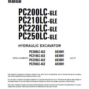
Komatsu PC200LC-6LE, PC210LC-6LE, PC220LC-6LE, PC250LC-6LE Excavator Repair Manual
$34.00
Manual Included:
- Shop Manual: 878 pages
Specifications:
- Brand: Komatsu
- Model: PC200LC-6LE, PC210LC-6LE, PC220LC-6LE, PC250LC-6LE
- Type: Excavator
- Serial Number: A83001 and up
- Manuals: Shop Manual
- Publication Number: CEBD001002 (June 2005)
- Language: English
- Format: PDF
- Description
- Reviews (0)
Description
Table of Content (Shop Manual)
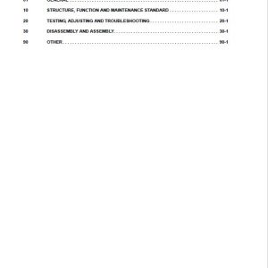
01 GENERAL . . . . . . . . . . . . . . . . . . . . . . . . . . . . . . . . . . . . . . . . . . . . . . . . . . . . . . . . . . . . . 01-1
10 STRUCTURE, FUNCTION AND MAINTENANCE STANDARD . . . . . . . . . . . . . . . . . . . . 10-1
20 TESTING, ADJUSTING AND TROUBLESHOOTING . . . . . . . . . . . . . . . . . . . . . . . . . . . . 20-1
30 DISASSEMBLY AND ASSEMBLY. . . . . . . . . . . . . . . . . . . . . . . . . . . . . . . . . . . . . . . . . . . 30-1
90 OTHER. . . . . . . . . . . . . . . . . . . . . . . . . . . . . . . . . . . . . . . . . . . . . . . . . . . . . . . . . . . . . . . . 90-1
GENERAL
This section lists the general machine dimensions, performance specifications, component weights, and fuel, coolant and lubricant specification charts.
STRUCTURE, FUNCTION AND MAINTENANCE STANDARD
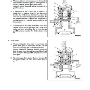
This section explains the structure and function of each component. It serves not only to give an understanding of the structure, but also serves as reference material for troubleshooting.
TESTING, ADJUSTING AND TROUBLESHOOTING
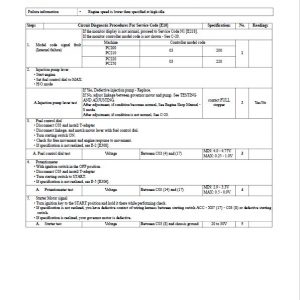
This section explains checks to be made before and after performing repairs, as well as adjustments to be made at completion of the checks and repairs. Troubleshooting charts correlating Problems to Causes are also mention in this section.
DISASSEMBLY AND ASSEMBLY KOMATSU
This section explains the order to be followed when removing, installing, disassembling or assembling each component, as well as precautions to be taken for these operations.
GOVERNOR MOTOR LEVER STROKE
1. Testing
★ Use the governor motor adjustment mode.
A. Preparatory work i. In the time mode display, keep the time switch + travel speed
R.H. switch + working mode R.H. switch pressed for 2.5 seconds.
★ On the 200 series, the engine output (135 PS) when the engine is
running at full throttle is the output when the power max. switch in the
active mode is ON, so use this mode instead of turning the power max. switch ON.
ii. Set the fuel control dial to MAX and the auto deceleration switch to OFF.
★ Any working mode can be used.
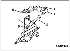
B. In this condition, check that governor lever (4) is in contact with FULL stopper (5) of the injection pump.
C. After checking, repeat the procedure in Step 1-A. to complete the governor motor adjustment mode.
2. Adjusting
A. Turn the starting switch OFF, then remove the nut and disconnect joint (1) from governor lever (4).
B. Repeat the procedure in Step 1-A. above to set to the governor motor adjustment mode.
C. Set governor lever (4) to a position where it contacts FULL stopper (5) of the injection pump, then adjust the length
of spring assembly (2) and rod (3), and connect joint (1) with the nut.
D. From the above position, turn rod (3) back 2 turns (retract the rod approximately 2.5 mm) and secure in position with
locknuts (6) and (7).
WARNING! When the spring assembly is removed and the starting switch is at the OFF position, if
the governor motor lever is moved suddenly, the governor motor will generate electricity,
and this may cause a failure in the governor controller.
Be the first to review “Komatsu PC200LC-6LE, PC210LC-6LE, PC220LC-6LE, PC250LC-6LE Excavator Repair Manual”
You must be logged in to post a review.


Reviews
There are no reviews yet.