

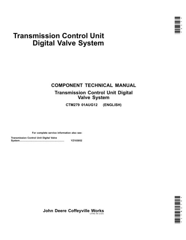
John Deere DF150, DF250 PowerShift Transmission Control Unit Component Technical Manual (CTM279)
$15.00
Manual Included:
- Component Technical Manual: 45 pages
Specifications:
- Brand: Funk/John Deere
- Applicable for: DF150, DF250
- Type: PowerShift Transmission Control Unit Component
- Manuals: Component Technical Manual
- Publication Numbers: CTM279
- Language: English
- Format: PDF
- Description
- Reviews (0)
Description
Table of Content (Component Technical Manual – CTM279)
Section 01—Transmission Control Unit
Group 05—Safety
Group 10—General Information
Group 15—System Component and Clutch Calibration
Group 20—Diagnostic Error Code
The purpose of the Funk DF150/250 Transmission Control Unit (TCU) is to control the functions of the transmission. Upshifting, downshifting, and control of the disconnect are the main functions. Other functions are the ability to drive a speedometer, and the capability to communicate with a panel mounted gear/diagnostic indicator. The transmission’s performance is determined by the various inputs to the TCU. Based upon these inputs, the TCU commands the transmission so that maximum performance can be achieved under the present operating conditions. All functions of the TCU are under software control. The Engagement Override Valve (EOV) and the Park Brake Solenoid functions are connected to the TCU, however these are not controlled by the TCU or software.
Operation begins when the vehicle’s ignition is switched to the on position, supplying electrical power to the TCU and related system components from the vehicle’s power source, through the transient voltage protection (TVP) module. The TCU now begins monitoring all inputs and outputs. If a known conflict in inputs or a fault condition is detected, the TCU will command the transmission to stay in neutral regardless of the shift lever position. A flashing error code will be displayed on the gear/diagnostic indicator, and will remain displayed until the error has been resolved and the shift lever cycled back through the neutral or park position. Whether the shift lever must cycle through the neutral position or the park position depends upon the shift lever that is in the system, and the vehicle manufacturer’s specifications.
If no error conditions are detected, the TCU will calculate a speed ratio between the engine RPM (derived from the engine speed MPU signal) and the transmission output speed (MPU). Based upon this speed ratio and the combination of inputs from the shift lever and any other applicable inputs, the TCU will select the proper transmission gear (not necessarily the gear as indicated by the shift lever) and command the transmission to shift to this gear. The gear/diagnostic indicator will now show the actual transmission gear.
The DF series of transmissions use electro-hydraulic valves to control the operation of the transmission. The solenoids controlling the transmission clutches (solenoids A through D & 1 through 4) are driven by a pulse width modulated (PWM) signal that produces proportional pressure/flow changes. This is achieved by pulsing the solenoid at a constant frequency and varying the “on time” of each cycle. The ratio of “on time” to cycle time is called duty cycle. These transmission solenoids are driven with a maximum duty cycle of 95% when full on. During modulation, the solenoids are started out with a duty cycle considerably less than this and ramped up to full on. The initial duty cycle is dependent upon several factors and is not a preset value. The process of modulating these clutches greatly enhances shift quality.
The solenoid controlling the disconnect function is not of the PWM type, but is of an on/off type. This solenoid is not modulated, and is driven by a 95% duty cycle when energized.
Be the first to review “John Deere DF150, DF250 PowerShift Transmission Control Unit Component Technical Manual (CTM279)”
You must be logged in to post a review.

Reviews
There are no reviews yet.