John Deere 5075M (FT4/Stage IIIB), 5085M (IT4/Stage IIIB) Tractors Repair Technical Manual
$62.00
Manual Included:
- Repair Technical Manual: 1423 Pages (TM116419)
- Diagnostic Technical Manual: 2629 Pages (TM116519)
- Operator’s Manual: 202 Pages (OMSJ14575)
Specifications:
- Brand: John Deere
- Model: 5075M (FT4/Stage IIIB), 5085M, 5100M, 5100MH, 5100ML, 5115M, 5115ML (IT4/Stage IIIB)
- Type: Tractor
- Manuals: Repair Technical, Diagnostic Technical Manual and Operator’s Manual
- Publication Numbers: TM116419, TM116519 and OMSJ14575
- Language: English
- Format: PDF
- Description
- Reviews (0)
Description
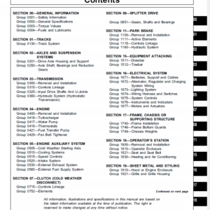
Table of Contents
Foreword
General Information
Safety
General References
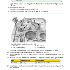
Technical Specific References
Diagnostic Trouble Codes
BCU Code Diagnostics
CCU Code Diagnostics
ECU Code Diagnostics
EIC Code Diagnostics
HCU Code Diagnostics
ICC Code Diagnostics
PTR Code Diagnostics
Observable Symptoms and System Diagnostics
General References
Engine Diagnostics
Fuel, Air Intake, Exhaust, and Cooling Diagnostics
Electrical Diagnostics
Electronic Control Unit Diagnostics
Drive Systems and Transmission Diagnostics
Steering and Brakes Diagnostics
Hydraulic Diagnostics
Cab/Open Operator`s Station Diagnostics Engine
General References
Engine Calibrations, Preliminary Checks and Operational Checks
Engine Theory of Operation
Engine Schematics
Engine Component and Connector Information
Engine Tests and Adjustments
Fuel, Air Intake, Exhaust, and Cooling
General References
Fuel, Air Intake, Exhaust, and Cooling Calibrations, Preliminary and Operational Checks
Fuel, Air Intake, Exhaust, and Cooling Theory of Operation
Fuel, Air Intake, Exhaust, and Cooling Schematics
Fuel, Air Intake, Exhaust, and Cooling Component and Connector Information
Fuel, Air Intake, Exhaust, and Cooling Tests and Adjustments
Electrical General and Theory of Operation
General References
Turn Signal Switch and Warning Lights
Wipers (Two Speed)
Wipers (Single Speed)
Rear Wipers
Instrument Cluster Control (ICC)
Basic Control Unit (BCU)
Electrohydraulic Control Unit (EHC)
Hitch Control Unit (HCU)
Power Train Reverser (PTR)
Chassis Control Unit (CCU) (PR/SR Transmission)
Chassis Control Unit (CCU) (SS Transmission)
Engine Control Unit (ECU)
Controller Area Network
Electrical Schematics
General References
Starting, Charging and Battery Disconnect (SE1)
Neutral Start (SS Transmission) (SE2A)
Neutral Start (PR/SR Transmission) (SE2B)
Accessory Power (SE3)
Horn (SE4)
Light Switch, Headlights, and Signal Lights (SE5)
Cab Work Lighting (SE5A)
Open Operator Station Work Lighting (SE5B)
Turn Signal Switch and Warning Lights (SE6)
Light Switch, Headlights and Signal Lights (License and Clearance Lights) (SE7)
Cab Work Lighting (License and Clearance Lights) (SE7A)
Open Operator Station Work Lighting (License and Clearance Lights) (SE7B)
Warning and Turn Signal Lighting (License and Clearance Lights) (SE8)
Junction Block Power (SE9)
Trailer Connector (SE10)
Trailer Connector (Implement Flood Light Connector) (SE11A)
Front Implement Interfaces (SE11B)
Loader Lights (SE12)
Back-Up Alarm (SE13A)
Beacon Light (SE13B)
Mid-Mount SCV (SE14)
Power Outlets (Square Terminals) (SE15A)
Power Outlets (Round Terminals) (SE15B)
Heating (SE16)
Air Conditioning (SE17)
Wipers (Two Speed) (SE19)
Wipers (Single Speed) (SE20)
Rear Wipers (SE21)
Dome Light, Door Switch, and Radio (SE22)
Air Seat (SE23)
Instrument Cluster Control (ICC) (SE24)
Ground Drive PTO, Seat, Rear PTO and Wheel Speed (SE25A)
Front PTO (SE25B)
Multi-Function Control Lever (SE25C)
ELX Relay and Fuses (SE26)
Mechanical Front-Wheel Drive (MFWD) (SE27)
Brake Switch (SE28)
Electrohydraulic Control Unit (EHC) (SE29A)
Hitch Control Unit (HCU) (SE29B)
Power Train Reverser (PTR) (SE29C)
Chassis Control Unit (CCU) (PR/SR Transmission) (SE29D)
Chassis Control Unit (CCU) (SS Transmission) (SE29E)
Engine Control Unit (ECU) (SE30)
Fuel Preheater (License and Clearance Lights) (SE31)
Controller Area Network (SE32)
Electrical Components and Connectors
General References
Starting and Charging (SE1)
Neutral Start (SS Transmission) (SE2A)
Neutral Start (PR/SR Transmission) (SE2B)
Accessory Power (SE3)
Horn (SE4)
Light Switch, Headlights, and Signal Lights (SE5)
Cab Work Lighting (SE5A)
Open Operator Station Work Lighting (SE5B)
Turn Signal Switch and Warning Lights (SE6)
Light Switch, Headlights and Signal Lights (License and Clearance Lights) (SE7)
Cab Work Lighting (License and Clearance Lights) (SE7A)
Open Operator Station Work Lighting (License and Clearance Lights) (SE7B)
Warning Light Switch and Turn Signal Lighting (License and Clearance Lights) (SE8)
Junction Block Power (SE9)
Trailer Connector (SE10)
Trailer Connector (Implement Flood Light Connector) (SE11A)
Front Implement (SE11B)
Loader Lights (SE12)
Back-Up Alarm (SE13A)
Beacon Light (SE13B)
Mid-Mount SCV (SE14)
Power Outlets (Square Terminals) (SE15A)
Power Outlets (Round Terminals) (SE15B)
Heating (SE16)
Air Conditioning (SE17)
Wipers (Two Speed) (SE19)
Wipers (Single Speed) (SE20)
Rear Wipers (SE21)
Dome Light, Door Switch and Radio (SE22)
Air Seat (SE23)
Instrument Cluster Control (ICC) (SE24)
Ground Drive PTO, Seat, Rear PTO, and Wheel Speed (SE25A)
Front PTO (SE25B)
Multi-Function Control Lever (SE25C)
ELX Relay and Fuses (SE26)
Mechanical Front-Wheel Drive (MFWD) (SE27)
Brake Switch (SE28)
Electrohydraulic Control Unit (EHC) (SE29A)
Hitch Control Unit (HCU) (SE29B)
Power Train Reverser (PTR) (SE29C)
Chassis Control Unit (CCU) (PR/SR Transmission) (SE29D)
Chassis Control Unit (CCU) (SS Transmission) (SE29E)
Engine Control Unit (ECU) (SE30)
Fuel Preheater (License and Clearance Lights) (SE31)
Controller Area Network (SE32)
Fuses and Relays
Ground Points
Interconnects
Wiring Harnesses
Electrical Tests and Adjustments
General References
Starting and Charging
Neutral Start (SS Transmission)
Neutral Start (PR/SR Transmission)
Accessory Power
Horn
Light Switch, Headlights, and Signal Lights
Cab Work Lighting
Open Operator Station Work Lighting
Turn Signal Switch and Warning Lights
Light Switch, Headlights and Signal Lights (License and Clearance Lights)
Cab Work Lighting (License and Clearance Lights)
Open Operator Station Work Lighting (License and Clearance Lights)
Warning and Turn Signal Lighting (License and Clearance Lights)
Junction Block Power
Trailer Connector
Trailer Connector (Implement Flood Light Connector)
Front Implement Interfaces
Loader Lights
Back-Up Alarm
Beacon Light
Mid-Mount SCV
Power Outlets (Square Terminals)
Power Outlets (Round Terminals)
Heating
Air Conditioning
Wipers (Two Speed)
Wipers (Single Speed)
Rear Wipers
Dome Light, Door Switch and Radio
Air Seat
Instrument Cluster Control (ICC)
Ground Drive PTO, Seat, Rear PTO, and Wheel Speed
Front PTO
Multi-Function Control Lever
ELX Relay and Fuses
Mechanical Front-Wheel Drive (MFWD)
Brake Switch
Electrohydraulic Control Unit (EHC)
Hitch Control Unit (HCU)
Power Train Reverser (PTR)
Chassis Control Unit (CCU) (PR/SR Transmission)
Chassis Control Unit (CCU) (SS Transmission)
Engine Control Unit (ECU)
Fuel Preheater
Controller Area Network
Electronic Control Units
General References
Calibrations, Preliminary Checks and Operational Checks
Theory of Operation
Schematics
Component and Connector Information
Tests and Adjustments
Basic Control Unit (BCU)
Chassis Control Unit (CCU)
Engine Control Unit (ECU)
Engine Interface Control Unit (EIC)
Hitch Control Unit (HCU)
Instrument Cluster Control Unit (ICC)
Power Train Reverser (PTR)
Drive Systems and Transmissions
General References
Calibrations, Preliminary Checks and Operational Checks
Creeper Theory of Operation
Differential Theory of Operation
Differential Lock Theory of Operation
Final Drive Theory of Operation
Front PTO Theory of Operation
Rear PTO Theory of Operation
High Crop Axle Theory of Operation
MFWD Theory of Operation
PR/SR Transmission Theory of Operation
PR Plus Transmission Theory of Operation
SS Transmission Theory of Operation
Drive Systems Schematics
Transmission Schematics
Drive Systems Component and Connector Information
Transmission Component and Connector Information
Drive Systems Tests and Adjustments
Transmission Tests and Adjustments
Steering and Brakes
General References
Brake Calibrations, Preliminary Checks and Operational Checks
Steering Calibrations, Preliminary Checks and Operational Checks
Brake Theory of Operation
Secondary Brake Theory of Operation
Steering Theory of Operation
Brake Schematics
Steering Schematics
Brake Component and Connector Information
Secondary Brake Component and Connector Information
Steering Component and Connector Information
Brake Tests and Adjustments
Secondary Brake Tests and Adjustments
Steering Tests and Adjustments
Hydraulics
General References
Calibrations, Preliminary Checks and Operational Checks
General Hydraulics Theory of Operation
Electrohydraulic Hitch Theory of Operation
Mechanical Hitch Theory of Operation
Front Hitch Theory of Operation
Hydraulic Filter Theory of Operation
Hydraulic Pump Theory of Operation
Dual Mid-Mount SCV Theory of Operation-Mono-Block Valve
Power Beyond Theory of Operation-Mono-Block Valve
Quick Disconnect Coupler Theory of Operation
Dual Rear SCV Theory of Operation-Mono-Block Valve
Triple Mid-Mount SCV Theory of Operation-Mono-Block Valve
Triple Rear SCV Theory of Operation-Mono-Block Valve
Dual Mid-Mount SCV Theory of Operation-Sectional Valve
Power Beyond Theory of Operation-Sectional Valve
Dual Rear SCV Theory of Operation-Sectional Valve
Triple Mid-Mount SCV Theory of Operation-Sectional Valve
Triple Rear SCV Theory of Operation-Sectional Valve
Hydraulic Trailer Brake Theory of Operation
Schematics-Mono-Block Valve
Schematics-Sectional Valve
Component and Connector Information
Tests and Adjustments
Cab/Open Operator`s Station
General References
Calibrations, Preliminary Checks and Operational Checks
HVAC Theory of Operation
Seat Theory of Operation
Schematics
Component and Connector Information
Tests and Adjustments
Special Tools
General References
Dealer Fabricated and Service Tools
Technical manuals are divided in two parts: repair and diagnostics. Repair sections tell how to repair the components. Diagnostic sections help you identify the majority of routine failures quickly.
This manual was planned and written for the Service Department; its place is in the shop. Use the manual whenever in doubt about correct maintenance procedures. Use it as a text book for training new Service Department personnel who are unfamiliar with John Deere Tractors.
Daily use of this Service Manual as a guide in overcoming service problems will reduce error and costly delay to a minimum and as-sure you the best in finished service work. In many instances your customer’s confidence in your work will be improved when he sees you using the Service Manual. He knows you are following approved maintenance procedures and making proper adjustments. There is no guess-work when you use the manual.
These are concise guides for specific-machines and are on-the-job guides-containing only the vital information needed for-diagnosis, analysis, testing, and repair.
Be the first to review “John Deere 5075M (FT4/Stage IIIB), 5085M (IT4/Stage IIIB) Tractors Repair Technical Manual”
You must be logged in to post a review.



Reviews
There are no reviews yet.