")
Hino Truck FD2J, FE2J, FF2J, SG1J, SG2J Year 2002 Repair Manual (FD, FE, FF, SG)
$36.00
This is the Repair and Service Manual for Hino Truck 2002
Series: FD, FE, FF, SG
Format: PDF
Language: English
- Hino 2002 Truck FD, FE, FF, SG Series Manual – 1528 Pages
- Hino J05D-TA Engine Manual – 324 Pages
- Hino J08E-TA & J08E-TB Engine Manual – 351 Pages
- Description
- Reviews (0)
Description
Hino Truck FD2J, FE2J, FF2J, SG1J, SG2J Year 2002 Repair Manual (FD, FE, FF, SG)
This is the Repair and Service Manual for Hino Truck 2002
Series: FD, FE, FF, SG
Format: PDF
Language: English
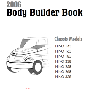
- Hino 2002 Truck FD, FE, FF, SG Series Manual – 1528 Pages
- Hino J05D-TA Engine Manual – 324 Pages
- Hino J08E-TA & J08E-TB Engine Manual – 351 Pages
This workshop manual has been prepared to provide information covering repairs on FD, FE, FF, SG series Hino 2002 trucks.
To use Hino 2002 trucks for years, smoothly, safely, and economically without trouble, it is important to perform inspections.
Maintenance required to be performed is the responsibility of the owner. Some recommended repairs of your truck are mentioned. When making any repair of your truck, be careful not to be injured through improper procedures.
As for maintenance items, refer to the Owners and Drivers Manual. All information and specifications in this manual are based upon the latest product information available at the time of printing.
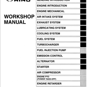
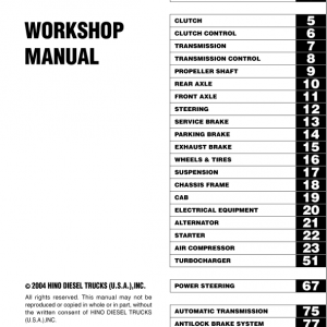
Table of Content For Hino 2002 Truck Manual:
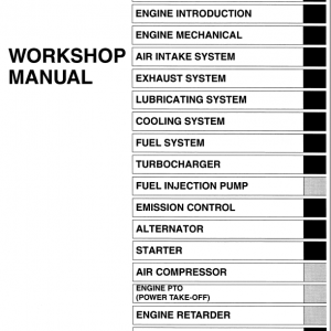
General Introduction
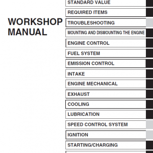
Engine
Clutch
Clutch Control
Transmission
Transmission Control
Propeller Shaft
Rear Axle
Front Axle
Steering
Service Brake
Parking Brake
Exhaust Brake
Wheels & Tires
Suspension
Chassis Frame
Cab
Electrical Equipment
Alternator
Starter
Compressor
Turbocharger
Spring Brake
Power Steering
Automatic Transmission
Antilock Brake System
Total Electronics System
Service Specification
Electrical Wiring Diagrams
Hino Truck 2002 Manual Instruction Extract:
 VALVE CLEARANCE CHECKING AND ADJUSTING PROCEDURES
If it out of the standard range, adjust the valve clearance using the following.
1. Before checking, make sure that the tightening bolts of the cylinder head, rocker support, nozzle clamp, cam housing and cam bearing cap are tightened to the specified torque.
2. Make sure that there are no foreign particles or dust between the cross head and the valve stem.
3. Turn the crankshaft in the forward direction to align the No. 1 piston to the top dead center of the compression stroke.
NOTE: Make sure that the roller is on the base circle of the camshaft.
In order to avoid that the cross head runs on the valve stem or that it comes off from the valve stem, turn the cross head to the right and left to ensure that the cross head correctly covers the valve stem by listening for the clicking sound.
4. Insert the feeler gauge between the rocker arm and the cross head and check that the valve clearance is within the standard range.
Valve clearace (when cold).
Intake valve : 0.30mm (0.0118 in.)
Exhaust valve : 0.45mm (0.0177 in.)
5. Loosen the adjusting screw nut of the cross head completely.
NOTE: The adjusting screw must protrude 10 mm (0.3937 in.) or more from the cross head upper face. Unless the adjusting screw is completely loose to the valve stem, the following adjustments may be adversely affected.
6. Insert a feeler gauge between the rocker arm and cross head. Adjust clearance with the adjusting screw of the rocker arm. Tighten the lock nut with the following torque.
7. With the feeler gauge inserted, loosen the adjusting screw of the cross head. Make sure that the feeler gauge does not feel loose.
NOTE: If it is loose, repeat these steps from 5.
8. Tighten the adjusting screw of the cross head until the feeler gauge does not move.
9. While loosening the adjusting screw of the cross head gradually, adjust the valve clearance. Tighten the lock nut of the cross head when the feeler gauge feels correct.
NOTE: The feeling of the feeler gauge during clearance adjustment is same as before.
Do not overloosen the adjusting screw.
Overloosening of the adjusting screw will cause the same condition as in 5 again. The feeler gauge may feel correct, but there may be excessive clearance between the adjusting screw of the cross head and the valve.
This does not allow for correct adjustment
Be the first to review “Hino Truck FD2J, FE2J, FF2J, SG1J, SG2J Year 2002 Repair Manual (FD, FE, FF, SG)”
You must be logged in to post a review.
Reviews
There are no reviews yet.