
Gehl Z80 Gen 2, Mustang 800Z Nxt 2 Compact Excavator Repair Service Manual
$42.00
Language: English
Format: PDF
Applicable for the Gehl Excavator Model Gehl Z80 Gen 2, Mustang 800Z Nxt 2
- Gehl Z80 Gen 2, Mustang 800Z Nxt 2 Excavator Repair Service Manual – 760 Pages
- Gehl Z80 Gen 2, Mustang 800Z Nxt 2 Excavator Operators Manual – 338 Pages
- Gehl Z80 Gen 2, Mustang 800Z Nxt 2 Excavator Parts Manual – 332 Pages
- Description
- Reviews (0)
Description
Key Chapters and Highlights
1. General Cautions for Maintenance Work
- Safety Precautions: Emphasizes correct maintenance practices to ensure safety and prevent damage.
- Handling Hydraulic Systems: Covers proper methods for handling hydraulic equipment, piping, seals, and hoses.
- Specifications: Includes specifications for hydraulic hoses and guidelines for air release in hydraulic systems.
2. Technical Data
- Specifications and Dimensions: Includes machine specifications, weight distribution, lifting capacities, and working area dimensions.
- Hydraulic and Wiring Diagrams: Provides schematic layouts for hydraulic circuits and electrical systems.
- Maintenance Schedule: Recommends periodic inspection, servicing, and lubricants.
3. Service Standards
- Performance Standards: Covers performance benchmarks for the engine, hydraulic systems, and undercarriage.
- Tightening Torques: Lists torque specifications for bolts, nuts, and hydraulic fittings.
- Pressure Adjustments: Includes procedures for adjusting relief valves and brake valves.
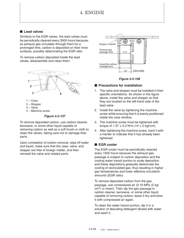
4. Engine
- Servicing Procedures: Detailed steps for servicing the engine, including valve adjustments, cylinder head work, and crankshaft maintenance.
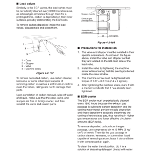
- EGR System and DPF: Covers emission control systems like the exhaust gas recirculation (EGR) system and diesel particulate filter (DPF) maintenance.
- Cooling and Lubrication Systems: Instructions for maintaining coolant pumps, oil pumps, and checking oil pressure.
- Troubleshooting: Provides troubleshooting guides for common engine issues.
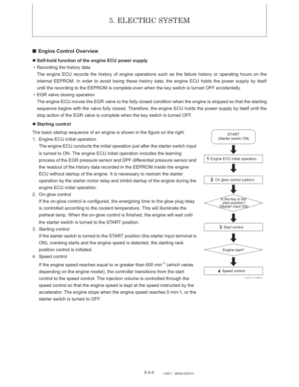
5. Electric System
- Electrical Components Layout: Details the location and function of electrical parts, including LCD monitors and alarm systems.
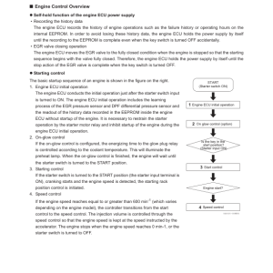
- Electronic Controls: Covers start/stop controls, engine ECU, and hydraulic ECU systems, including SMARTASSIST DIRECT (SA-D) functionality.
- Error Codes: Includes a comprehensive list of error codes and diagnostic tools.
6. Hydraulic System
- Circuit Operations: Explains the hydraulic functions for boom, arm, bucket, blade, swing, and travel systems.
- Pump and Valve Maintenance: Details servicing hydraulic pumps, control valves, and solenoid valves.
- Simultaneous Operations: Explains the handling of complex operations like combined boom and swing actions.
- Troubleshooting: Diagnoses common hydraulic system issues.
7. Adjustment and Repair
- Component Removal and Reinstallation: Guides for key components, including the engine, hydraulic pump, and cabin.
- Undercarriage Maintenance: Covers crawler removal, travel motor servicing, and reassembly of idlers and rollers.
- Hydraulic Cylinder Repair: Provides detailed instructions for disassembling, reassembling, and inspecting hydraulic cylinders.
- Air Conditioning: Includes steps for removing and reinstalling air conditioning systems.
8. Troubleshooting
- Non-Breakdown Issues: Addresses minor operational problems like bucket release and arm movement irregularities.
- Quick Reference Tables: Offers tables for diagnosing and resolving common machine issues.
Be the first to review “Gehl Z80 Gen 2, Mustang 800Z Nxt 2 Compact Excavator Repair Service Manual”
You must be logged in to post a review.

Reviews
There are no reviews yet.