


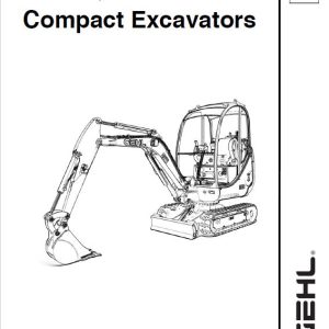
Gehl Z55, Mustang 550Z Compact Excavator Repair Service Manual
$42.00
Language: English
Format: PDF
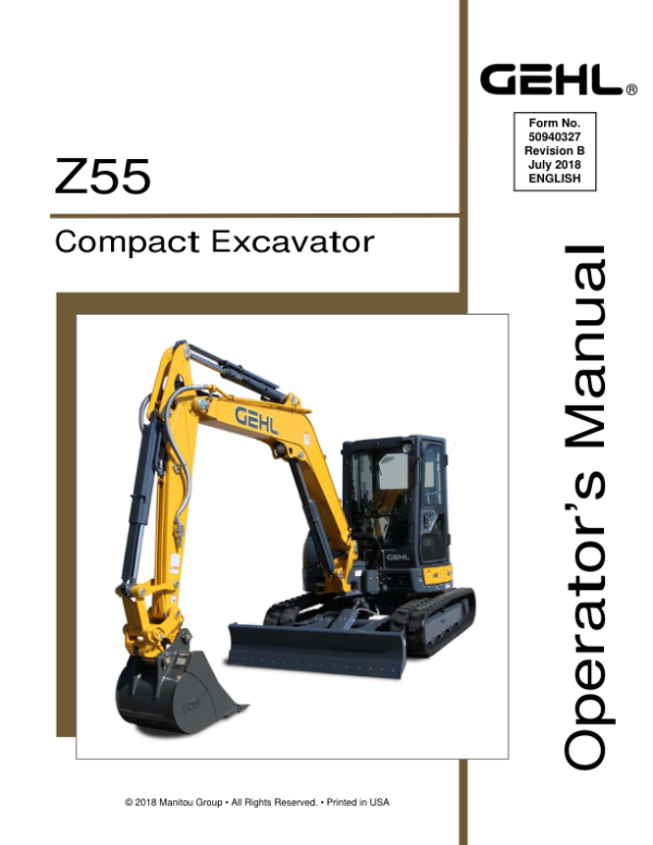
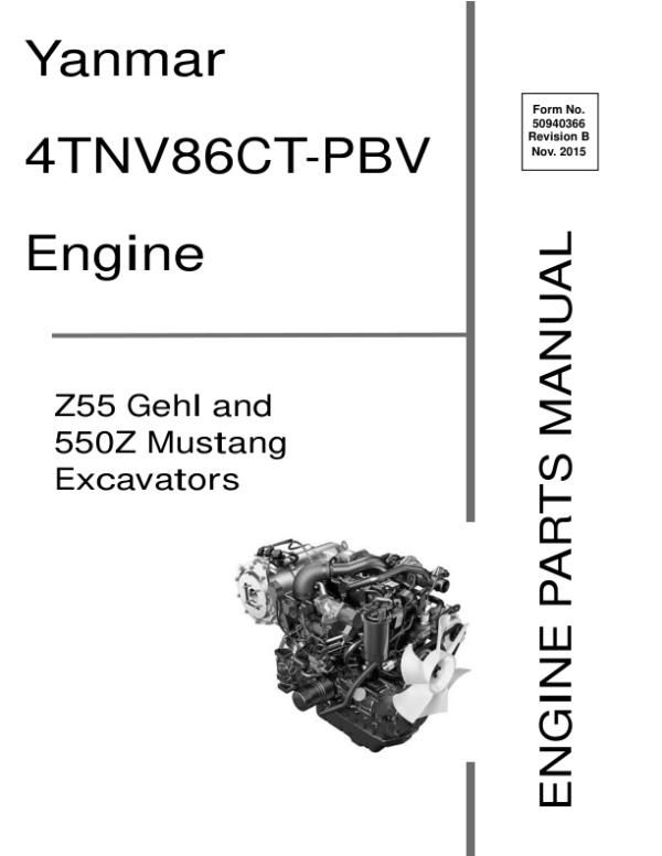
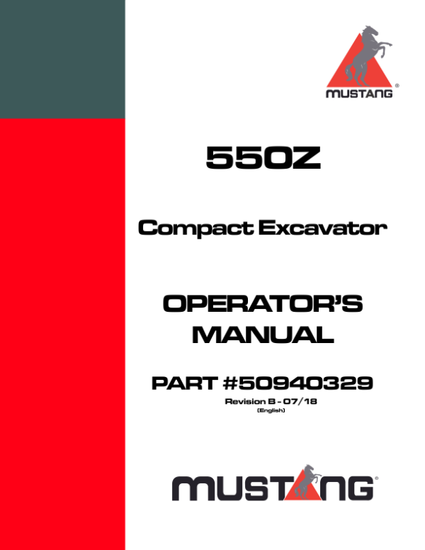
Applicable for the Gehl Excavator Model Gehl Z55, Mustang 550Z
- Gehl Z55, Mustang 550Z Excavator Repair Service Manual – 760 Pages
- Gehl Z55, Mustang 550Z Excavator Operators Manual – 342 Pages
- Gehl Z55, Mustang 550Z Excavator Parts Manual – 430 Pages
- Description
- Reviews (0)
Description
Key Chapters and Highlights
- General Cautions for Maintenance Work:
- Includes safety precautions, proper preparation, and handling instructions for hydraulic equipment, seals, and hoses.
- Emphasizes correct disassembly and reassembly techniques to prevent damage.
- Technical Data:
- Details machine specifications, weight distribution, lifting capacities, and working area dimensions.
- Provides hydraulic circuit schematics, wiring diagrams, and lubricant recommendations.
- Outlines periodic inspection and servicing schedules.
- Service Standards:
- Contains performance standards for the engine, hydraulic systems, and undercarriage.
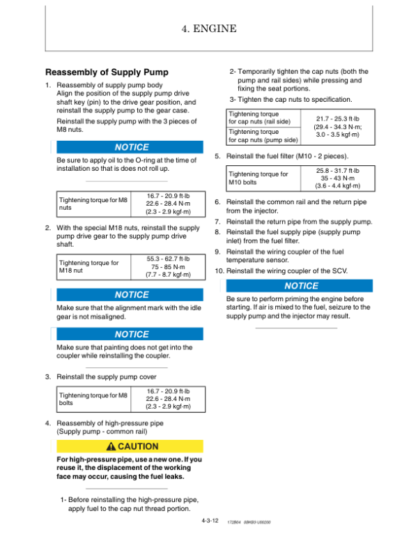
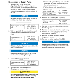
- Includes tightening torque values for various components and pressure adjustment guidelines for hydraulic fittings.
- Lists nominal and allowable values for critical machine components.
- Engine:
- Covers detailed servicing procedures, including valve clearance adjustments, EGR system servicing, and crankshaft maintenance.
- Includes guidance on fuel, cooling, and lubrication systems, as well as turbocharger maintenance.
- Provides troubleshooting charts and wiring diagrams for engine components.
- Electric System:
- Layout and function of electrical components, including LCD monitors and alarm systems.
- Details electronic control systems for start/stop operations, auto deceleration, and eco modes.
- Includes error code lists and troubleshooting techniques.
- Hydraulic System:
- Detailed circuit operations for boom, arm, bucket, swing, and blade functions.
- Instructions for simultaneous operation scenarios and optional systems such as quick couplers and hydraulic P.T.O.
- Maintenance and repair procedures for pumps, valves, and motors.
- Adjustment and Repair:
- Removal and reinstallation instructions for key components like the engine, undercarriage, and cabin.
- Procedures for repairing hydraulic cylinders, swivel joints, and the diesel particulate filter (DPF).
- Provides detailed layouts and diagrams for piping and jigs.
- Troubleshooting:
- Diagnostic guides for common issues, such as bucket release, arm movement irregularities, and travel motor thermal shocks.
- Quick reference tables for identifying and addressing breakdown causes.
- Instructions for resolving hydraulic oil fluctuations and quick coupler operation issues.
Be the first to review “Gehl Z55, Mustang 550Z Compact Excavator Repair Service Manual”
You must be logged in to post a review.


Reviews
There are no reviews yet.